



Content last revised on September 28, 2026
Benchtop Waveform Tuning and Baseplate Thermal Contact on 6MBP150RTC060A
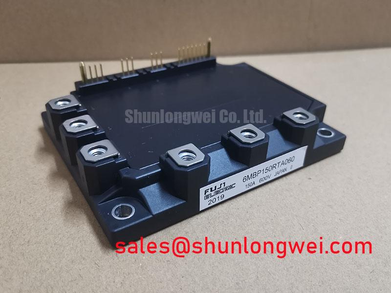
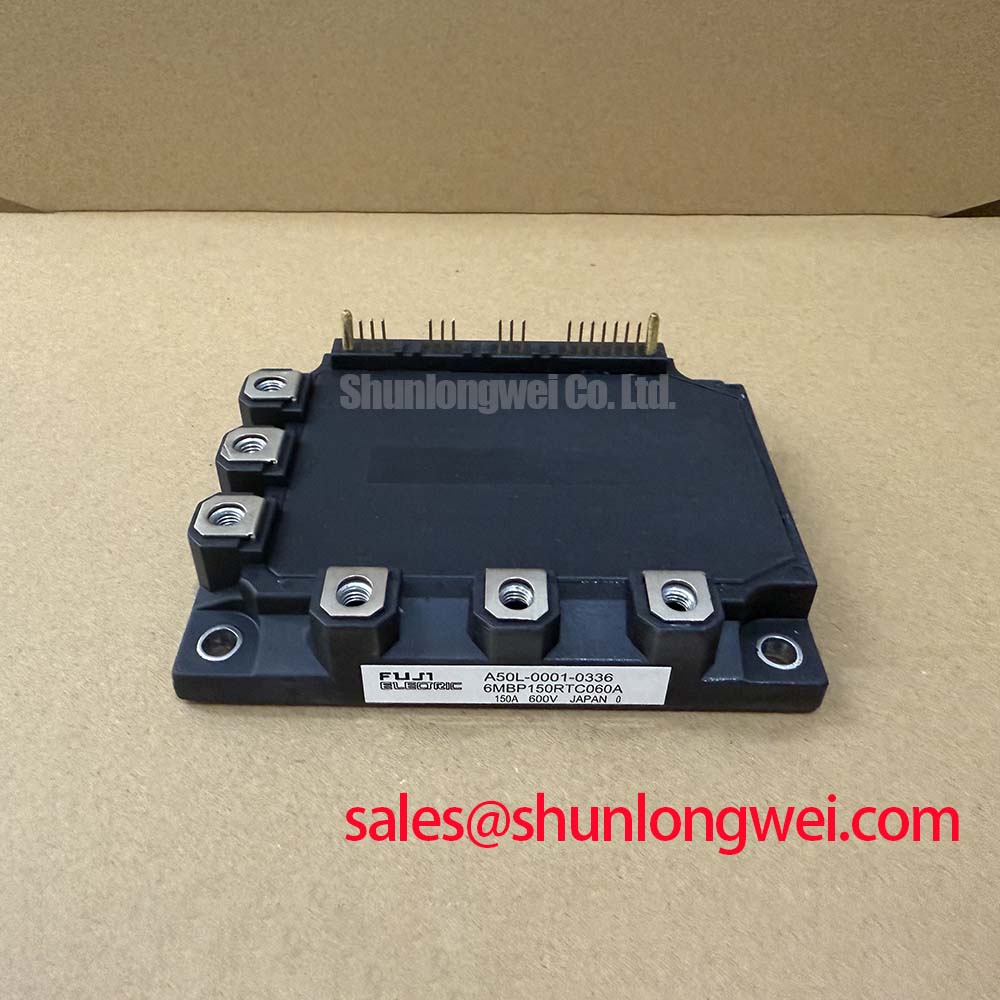
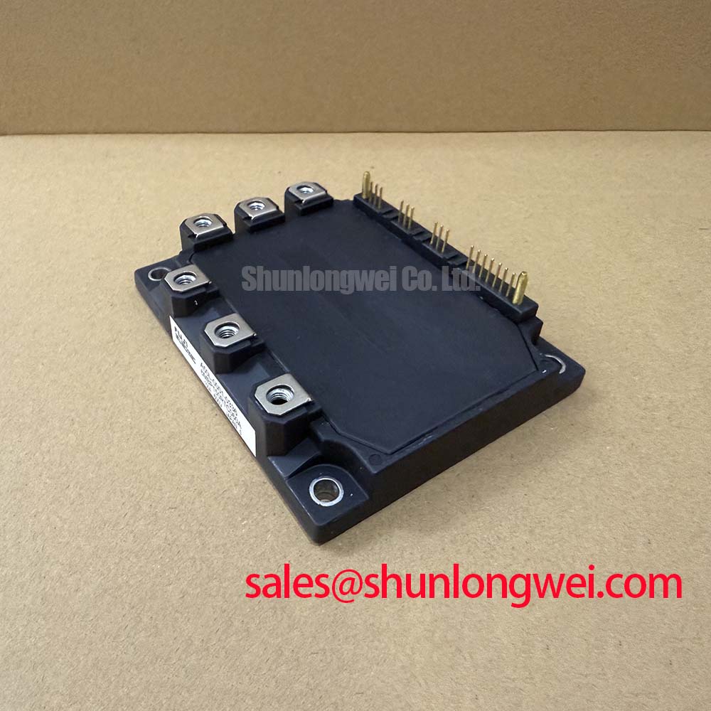
With the drive isolated and the DC link discharged, compare the cold terminal readings of the 6MBP150RTC060A against the equipment schematic before mounting it. Confirm the terminal identities from the original module documentation rather than inferring them from the layout of a removed unit. A multimeter diode check can help identify expected freewheeling-diode conduction paths and reveal a gross short, but its reading is not a substitute for a measured forward-voltage test at the datasheet conditions.
Fuji Electric specifies the module’s collector-emitter voltage as 600 V and its DC collector current as 150 A at a case temperature of 80°C (Official Datasheet Specifications). The 300 A collector-current pulse rating applies to a 1 ms pulse; it is not a continuous operating allowance. Before using any of these ratings to qualify a repair, check the installed DC-link voltage, cooling arrangement and fault-clearing behavior against the original equipment design.
💡 Bench Tip: Keep the gate terminals protected from electrostatic discharge during incoming inspection, and compare cold diode-mode readings with a documented, known-good unit rather than treating one meter value as a universal pass limit.
After electrical inspection, examine the mating heatsink and module baseplate for contamination, scoring or uneven contact. As a Design Consideration, apply thermal interface material as a controlled, thin layer rather than using extra compound to conceal a poor mounting surface. Remove visible trapped air and check whether baseplate curvature or heatsink flatness prevents uniform contact. Tighten the mounting screws progressively in the sequence specified by the applicable mechanical documentation, then confirm that the assembly sits evenly. A nominal grease thickness or generic screw torque should not be presented as a Fuji Electric requirement for this model without its mounting specification.
If switching waveforms deteriorate after a module change, inspect the thermal joint and gate-drive connections separately. Poor thermal contact can raise operating temperature, while changed loop geometry can alter switching behavior; one observation does not establish the other as its cause. During a controlled power-up, record the gate waveform and collector-emitter voltage at the same operating point used for the previous assembly. Keep measurement leads short enough to avoid mistaking probe pickup for a device transient, and have the system engineer verify observed voltage peaks against the 600 V device rating with appropriate transient margin.
Transient Dynamics and Junction-to-Case Thermal Response of 6MBP150RTC060A
Record the case temperature near the module and the load-current profile before assessing a pulsed overload. The official junction-to-case thermal resistance is 0.24°C/W per IGBT; the stated collector power dissipation is 520 W per IGBT, and the maximum specified junction temperature is +150°C (Official Datasheet Specifications). These values describe different boundaries. In particular, multiplying a brief pulse’s power by the steady-state thermal resistance does not describe its complete transient temperature rise.
| Datasheet parameter | Published value and condition | Use during evaluation |
|---|---|---|
| Collector-emitter voltage, VCES | 600 V | Check measured switching peaks as well as DC-link voltage. |
| DC collector current, IC | 150 A at Tc = 80°C | Check the case-temperature condition before comparing current. |
| Pulse collector current, ICP | 300 A for 1 ms | Do not treat the pulse rating as a repetitive-duty approval. |
| Junction-to-case resistance, Rth(j-c) | 0.24°C/W per IGBT | Use with an appropriate loss and thermal model. |
| Maximum specified junction temperature, Tj | +150°C | Compare the modeled peak with this device limit. |
For repeated pulses, an Engineering Calculation should use the device-specific transient thermal impedance curve or a validated multi-RC model, together with the measured loss waveform and case-temperature history. No transient impedance curve or RC coefficients are supplied in the specifications above, so a numerical peak junction temperature cannot be responsibly assigned here. Likewise, the heatsink, enclosure airflow and ambient temperature are system inputs, not properties that the module rating alone settles.
At the specified test point of 150 A collector current and 15 V gate-emitter voltage, collector-emitter saturation voltage is 2.1 V typical and 2.7 V maximum (Official Datasheet Specifications). Those figures are useful for checking the conditions behind a conduction-loss estimate; they do not establish an in-circuit voltage limit at every temperature and current. The freewheeling-diode forward voltage is 1.95 V typical and 2.5 V maximum (Official Datasheet Specifications). When estimating a bidirectional energy-storage converter’s thermal duty, account for the measured direction and duration of current through each conducting path rather than applying one loss figure to the entire operating cycle.
The published switching times are 0.50 µs typical turn-on at 150 A and 300 V, and 0.55 µs typical turn-off (Official Datasheet Specifications). They are comparison points, not switching-loss values or approval for a particular operating frequency. Designers evaluating higher-frequency operation should measure switching energy under the intended gate drive and cooling conditions, then revisit the junction-temperature estimate. Fuji Electric’s V-Series IGBT Application Manual provides general application context for thermal and switching evaluation; its guidance should not be mistaken for missing model-specific transient data.
Preventing Spurious Faults Through Parameter and Gate-Loop Checks
When a repaired inverter trips under load, first compare its logged current, case temperature and fault timing with a controlled run at a lower load. A static diode-mode check may rule out an obvious short while leaving a temperature-dependent or switching-related problem unresolved. Scope the gate-emitter and collector-emitter waveforms at accessible, appropriately isolated measurement points, and compare them with the equipment’s documented reference behavior.
The published VCE(sat) values belong to the stated 150 A and 15 V test condition. They do not establish a temperature coefficient for this particular module. If a design places switching devices in parallel, a Design Consideration is to evaluate both steady-state current sharing and dynamic balance using the relevant temperature-characteristic data and measured waveforms. Match the physical gate-loop paths where the equipment topology calls for parallel operation, and verify the result under the system’s actual drive conditions. Do not assume a dedicated Kelvin-emitter terminal exists on the 6MBP150RTC060A without confirming the original pinout.
Inspect the drive board for changed isolation components, damaged connectors and altered return paths before attributing an unexpected trip to the power module. Common-mode transients can disturb a drive signal if the installed optocoupler or digital isolator and its layout are unsuitable for the measured switching environment. The appropriate response is to check that component’s documented common-mode transient immunity and observe the drive signal during the event; there is no model-specific isolator rating in the module specifications provided here. Maintain the equipment’s documented electrical clearances and let its qualified design documentation determine whether any board modification is permissible.
For a commercial string inverter or micro-grid energy-storage repair, compatibility remains a system-level question: compare the existing module’s electrical ratings, terminal map, mounting interface, drive arrangement and protection behavior. The 6MBI100L-060 can be reviewed as a separate Fuji Electric device during that comparison, but its different model designation does not establish direct interchangeability. Similarly, the 6MBI15L-060 is a separate module that may appear in a wider equipment bill of materials; its role in any particular power stage must be confirmed from the equipment schematic. Fuji Electric’s power-semiconductor product information offers manufacturer context, not approval to exchange modules without that check.
Desaturation Detection and Controlled Fault Turn-Off
Before restoring full load, identify how the installed drive board senses an overcurrent or desaturation event. Trace the sense connection, its reference return and the path that commands turn-off; then compare the observed fault sequence with the drive-board schematic. The supplied 6MBP150RTC060A specifications do not state an integrated desaturation threshold, short-circuit withstand time or soft-turn-off profile. Those functions must not be assumed to reside inside the module.
Desaturation detection is a system Design Consideration because collector-emitter voltage can rise when an IGBT is driven on but cannot support the demanded current under its operating conditions. A protection circuit must distinguish a real fault from normal turn-on behavior, while its turn-off action must avoid excessive inductive voltage overshoot. The required sensing delay, threshold and turn-off shape depend on the installed gate drive and power-loop inductance; the system engineer should verify them with the applicable device protection data and instrumented switching tests, rather than assigning an unsupported timing limit to this model.
If a nuisance trip follows a module installation, check sense wiring and gate-drive supply behavior before changing protection settings. Compare the fault indication with simultaneous gate and collector-emitter traces: a disturbance on the sense path, an interrupted drive command and a genuine rise in on-state collector-emitter voltage can call for different repairs. After an actual fault, repeat the isolated cold terminal checks and inspect the cooling interface before another controlled energization. The The Ultimate IGBT Knowledge Base gives background on IGBT switching and fault mechanisms, while the equipment schematic and model-specific limits remain the references for the repair decision.