

Content last revised on September 27, 2026
7MBR100SB060-50 Gate-Drive Checks and Active Miller Clamp Tuning
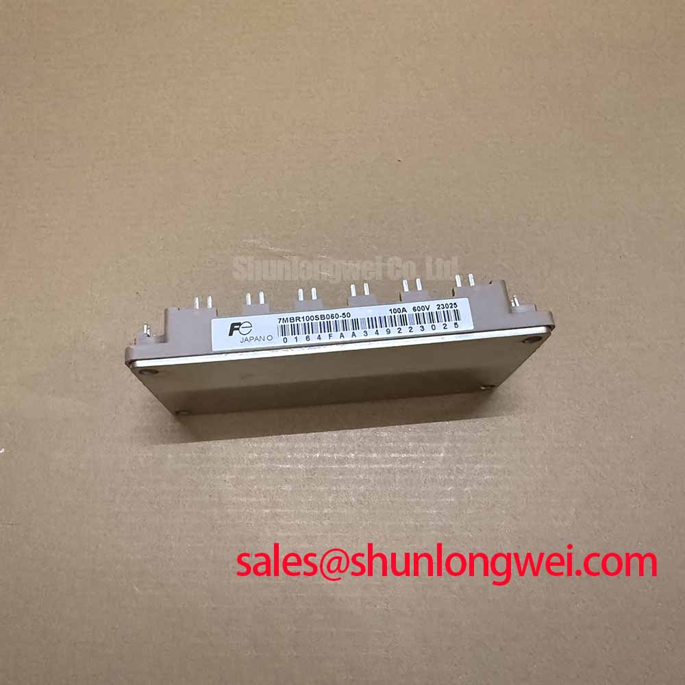
With the DC bus isolated and discharged, compare the cold diode-mode readings at the power terminals of 7MBR100SB060-50 against the original equipment wiring diagram before connecting a gate driver. Record the meter polarity for each reading: a repeatable forward reading in one direction and a different reading in the other is more useful than an unlabelled value. The module is a Fuji Electric power module with an inverter section rated at 600 V collector-emitter voltage and 100 A DC collector current at a case temperature of 25°C, according to the supplied official specifications. Those ratings identify electrical boundaries; they do not establish terminal compatibility or suitability for a particular machine.
Start gate-drive assessment at the equipment schematic, not at a familiar-looking module outline. Identify each gate and emitter connection from the original module documentation, then trace its driver path and power-return path separately. A diode-mode check can help establish a cold baseline for accessible power paths, but it cannot verify switching behaviour, gate insulation, or the health of every parallel circuit in an assembled machine. Compare suspect readings with a documented known-good unit using the same meter and polarity before drawing a conclusion.
The supplied official specifications list a typical collector-emitter saturation voltage of 1.70 V at a collector current of 100 A. That is an operating-condition specification, not a target for a handheld meter’s diode mode. Likewise, the inverter section’s 430 W total power dissipation is a rated boundary, not permission to dissipate that power continuously without assessing case temperature and the installed thermal path. Keep the conditions attached to these figures when comparing a repair candidate with an equipment bill of materials.
Design Consideration: when the opposite switch in a bridge commutates, voltage changing across an off-state IGBT can couple into its gate circuit. An active Miller clamp offers a low-impedance path intended to restrain that gate rise. Whether the existing driver uses a clamp, a negative off-state bias, or another arrangement must be established from the equipment schematic; none of those features should be attributed to the module without its confirmed terminal documentation. At the bench, observe the off-state gate-to-emitter waveform and the switching-node waveform together. A gate excursion coincident with commutation warrants checks of the driver return, clamp connection, probing arrangement, and power-loop layout rather than an immediate diagnosis of shoot-through.
Engineering Recommendation: preserve a short, deliberate gate-drive return path and evaluate damping from measured switching waveforms. Do not assume an auxiliary Kelvin-emitter terminal exists on 7MBR100SB060-50; confirm the terminal drawing before assigning any emitter connection that role. If the equipment uses a bootstrap high-side supply, check its charging opportunity under the actual switching pattern and observe supply droop during operation. The bootstrap capacitor and diode belong to the driver design, so their capacity and recovery requirements are system-determined.
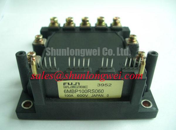
For a cross-check during part evaluation, 6MBI100L-060 provides another Fuji Electric module listing to examine. A matching headline current or voltage does not establish interchangeability: compare terminal assignments, circuit topology, mounting interface, driver requirements, and the applicable manufacturer documentation first. Fuji Electric’s high-speed discrete IGBT information is useful background on IGBT device behaviour, but discrete-device information should not be treated as the specification for this module.
Benchtop Waveform Tuning: Output Reflections and Switching Stress
Capture the inverter output waveform at the module-side terminals and, where access and safe measurement practice permit, at the far end of the connected cable. Long leads and a fast voltage edge can produce a reflected wave when the cable and load impedances differ. A high terminal peak may therefore depend on cable length, edge rate, and measurement location; it is not a fixed characteristic of 7MBR100SB060-50. Compare captures under the same operating condition before deciding whether a changed peak came from the module, wiring, or load.
Design Consideration: an output filter or choke can moderate the edge reaching a long cable, but its selection must account for the actual load current, switching pattern, thermal environment, and acceptable output waveform. The system engineer should verify the resulting peak voltage at relevant terminals against the complete equipment ratings. Industrial inverter welders and medium-frequency induction-heating supplies are possible contexts for this evaluation, subject to their particular power-stage topology; neither application is established by the module part number alone.
Keep output-cable reflections distinct from DC-link ripple. If the supply waveform varies with line phase, inspect the rectifier, bulk capacitance, and load-current trace before changing the inverter gate circuit. Phase-angle control in upstream equipment can alter the observed bus waveform, while rectification and filtering determine how much of that variation reaches the inverter. The supplied official specifications give the module’s rectifier section a 100 A DC forward-current rating; they do not specify an external smoothing capacitor or a permissible ripple for an assembled supply.
An RC snubber may be evaluated where measured ringing calls for transient suppression. Place probes so the measurement loop does not create a misleading spike, then compare peak voltage, ringing, and snubber temperature across the intended operating range. Snubber values and placement are system decisions. In a review of related Fuji Electric power-stage parts, 6MBI100S-140 can be examined as a separate module listing; its circuit role, ratings, and driver needs must be checked independently rather than inferred from this module’s rectifier rating.
7MBR100SB060-50 Thermal Interface and Mounting Checks
Inspect the heatsink contact area before treating an elevated case temperature as an electrical fault. Look for contamination, uneven compound transfer, and fasteners that appear to have been tightened unevenly. Record the original mounting arrangement and check the equipment service instructions for the approved compound, fastener sequence, and torque. The supplied official parameters do not state a mounting torque or a required thermal-interface thickness for 7MBR100SB060-50.
Design Consideration: thermal compound should fill surface irregularities without becoming an unnecessarily thick barrier. Apply it evenly, seat the module without trapping visible voids, and tighten fasteners progressively using the documented mounting procedure. Do not attempt to compensate for a visibly distorted mounting surface with extra compound; inspect the heatsink and module contact surfaces against the relevant mechanical documentation instead. Thermal-paste condition is one possible contributor to rising temperature, not a diagnosis on its own.
💡 Bench Tip: Keep the driver disconnected during cold power-terminal checks, and follow the equipment discharge procedure before touching or moving the module.
The specified 2500 V AC isolation voltage for one minute is an official module rating. It is not an instruction to apply that test indiscriminately to installed equipment: connected control electronics, contamination, and the machine’s approved test procedure all matter. For incoming inspection, record the marking, accessible terminal condition, and mounting-face condition, then use only an insulation test method authorized for the assembly. A passed cold resistance check cannot establish long-term insulation reliability.
When temperature readings differ from a known-good installation, compare them at matched load and cooling conditions. Check heatsink airflow or coolant flow, contact pressure, sensing position, and electrical losses before attributing the change to the semiconductor alone. The 430 W inverter dissipation rating and the typical 1.70 V saturation figure serve different purposes and cannot be combined into an installed operating-temperature guarantee. For broader gate-drive and thermal-path principles, the IGBT Design & Integration guide provides context alongside the module-specific checks.
7MBR100SB060-50 DC-Bus Layout and Turn-Off Overshoot Checks
Trace the DC-link current path physically, from the local capacitor connections through the module terminals and back. A schematic can conceal a long or asymmetric connection that is obvious on the bench. During turn-off, current changing through stray loop inductance adds voltage to the DC-link level seen by a switching device. That relationship explains why a measured peak can rise even when the steady bus voltage has not changed; the permissible layout and snubber arrangement still have to be established by tests on the actual equipment.
Design Consideration: keep opposing DC-bus current paths close and symmetrical where the equipment geometry permits, to reduce inductive overshoot. A laminated busbar is one possible implementation, not a feature of the module. Check terminal alignment and required electrical clearances against the assembly drawings before altering a bus structure. Avoid assigning an inductance target or clearance dimension from the module’s 600 V collector-emitter rating alone.
Measure bus voltage and switching peak with probes and connections appropriate to the circuit, then repeat at operating conditions that expose the highest observed stress. If a peak changes after a busbar repair, inspect the current path, capacitor connections, probe loop, and gate waveform before crediting a single cause. A local snubber capacitor can be considered to limit transient voltage, but its value, current capability, placement, and thermal behaviour require system-level verification. The useful endpoint is a documented peak-voltage margin under the equipment’s tested conditions, not an assumed margin derived from a cold meter reading.