


Content last revised on March 30, 2026
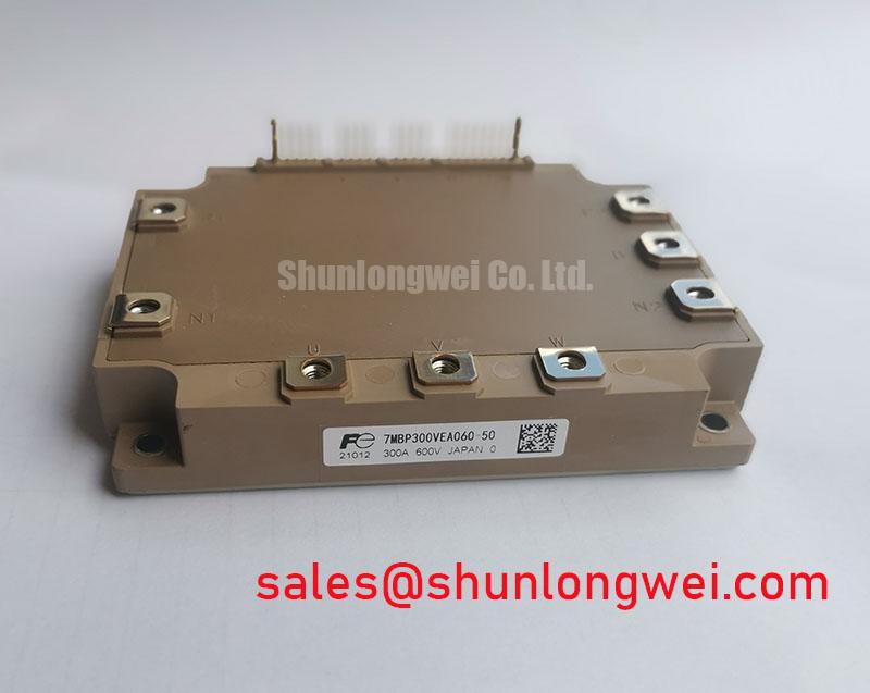
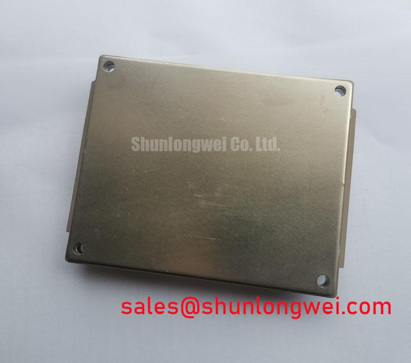
7MBP300VEA060-50 PIM Module: An Engineer's Guide
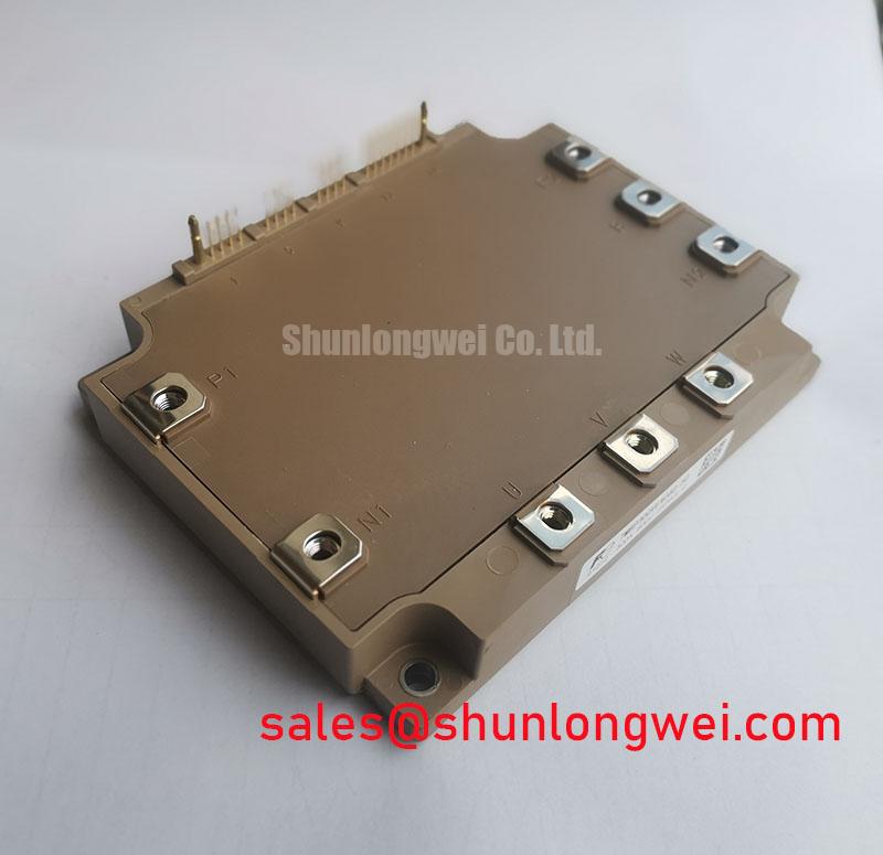
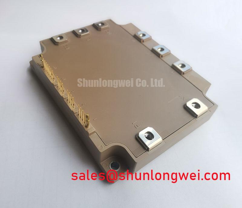
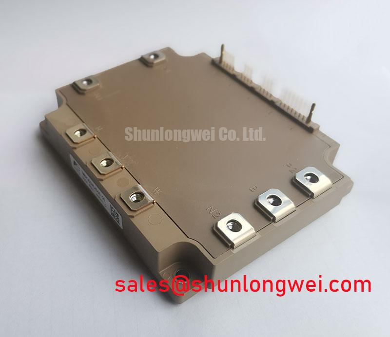
Accelerating motor drive development, the Fuji Electric 7MBP300VEA060-50 PIM integrates a complete 7-in-1 power stage for streamlined system design. This V-Series Power Integrated Module (PIM) combines a three-phase converter, inverter, and brake circuit, significantly reducing component count. How does using a 7-in-1 IGBT module simplify motor drive design? By consolidating the entire power core, it reduces PCB complexity, shortens assembly time, and minimizes potential points of failure inherent in discrete designs.
Top Specs: 600V | 300A (Inverter) | Tj(max) 150°C
Key Benefits: Simplified BoM and assembly. Enhanced system-level reliability.
A Case Study in Simplified Assembly
Consider the design of a mid-power industrial motor drive. A traditional approach requires sourcing, qualifying, and assembling numerous discrete components: six rectifier diodes, six inverter IGBTs with corresponding freewheeling diodes, a brake chopper IGBT and diode, plus an external NTC for thermal feedback. This process involves complex PCB routing for high-current paths, careful gate drive layout, and mechanical mounting of multiple devices to a heatsink.
By implementing the 7MBP300VEA060-50, this entire subsystem is reduced to a single component. The engineering team can focus on control logic and interface design rather than power stage layout intricacies. This consolidation directly translates to fewer manufacturing steps, reduced inventory management, and a faster path from prototype to production. The inherent reduction in soldered connections and wiring also contributes to a more robust final product with a longer operational lifespan.
Strategic Advantages of PIM Integration in Modern Power Systems
The industry's push towards higher power density and lower Total Cost of Ownership (TCO) makes integrated solutions like the 7MBP300VEA060-50 strategically valuable. A Power Integrated Module (PIM) moves beyond simple components to become a pre-validated power subsystem. This approach offers significant advantages:
- Reduced R&D Cycles: By providing a proven thermal and electrical layout internally, the PIM mitigates risks associated with parasitic inductance and component matching that are common in discrete designs.
- Improved Serviceability: In the field, diagnosing and replacing a single module is far more efficient than troubleshooting and replacing individual power semiconductors, minimizing downtime for critical machinery.
- Supply Chain Simplification: Sourcing a single, highly integrated module streamlines procurement and reduces dependencies on multiple component suppliers. This simplifies inventory and mitigates risks of line-down situations due to the shortage of a single diode or transistor.
Datasheet Comparison: Evaluating Integration Levels
For engineers evaluating power stage options, it's crucial to compare components based on their level of integration and how that aligns with project goals. The data below is provided to support a fact-based decision process.
| Parameter | Fuji Electric 7MBP300VEA060-50 | Typical Discrete Solution | Alternative Module (e.g., 6-Pack) |
|---|---|---|---|
| Configuration | 7-in-1 (Converter + Brake + Inverter) | 15+ discrete power components | 6-in-1 (Inverter only) |
| Built-in Thermistor | Yes (NTC) | Requires external component | Often included |
| Required PCB Area | Minimal (single component footprint) | Substantial (multiple components + layout) | Moderate (module + external rectifier/brake) |
| Assembly Steps | Single component placement | Multiple placements and soldering steps | Multiple module/component placements |
Note: This comparison is for illustrative purposes. All specifications should be verified against official datasheets for your specific application.
Core Applications: Where Integrated Design Delivers Maximum Value
The highly integrated architecture of the 7MBP300VEA060-50 is engineered to add significant value in applications where space, assembly cost, and reliability are key design drivers. Its electrical characteristics and physical consolidation make it a prime candidate for:
- Variable Frequency Drives (VFDs): The 7-in-1 topology provides the complete power core for AC motor control, simplifying the design of compact and robust drives for conveyors, pumps, and HVAC systems.
- Servo Drives: In robotics and CNC machinery, the module's integrated nature contributes to smaller drive cabinets and improved reliability, which is essential for precision motion control. For systems with different voltage requirements, the 2MBI600VE-120-50 offers a 1200V alternative.
- General Purpose Inverters: From industrial power supplies to small-scale renewable energy converters, this PIM offers a plug-and-play power stage that accelerates development.
What is the best fit for this module? For industrial motor drives up to ~150 kW requiring a complete, pre-engineered power stage to shorten design time, the 7MBP300VEA060-50 is an optimal choice due to its 7-in-1 integration.
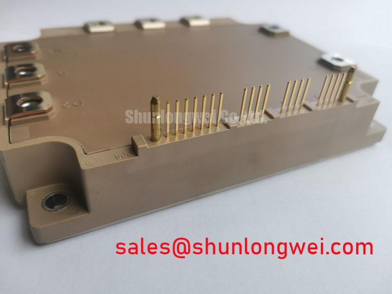
Technical Teardown of the 7-in-1 Architecture
The 7MBP300VEA060-50 is more than just a collection of switches; it's a carefully engineered power conversion block. Internally, it is comprised of three main sections built upon Fuji Electric's V-Series IGBT technology, which is designed for a favorable balance between conduction and switching losses.
Converter Section
A three-phase diode bridge rectifier forms the input stage. This section converts the incoming AC supply into a DC bus voltage, providing the power source for the inverter. Its robust design is matched to the current handling capabilities of the inverter stage.
Inverter Section
The core of the module is a three-phase bridge of six IGBTs and six co-packaged Freewheeling Diodes (FWDs). This stage performs the DC-to-AC power conversion, generating the variable frequency and voltage output required to control motor speed and torque.
Brake Section
An integrated brake chopper, consisting of a single IGBT and an FWD, allows for the controlled dissipation of regenerative energy from the motor. This is critical during deceleration, preventing DC bus overvoltage and ensuring system stability without the need for an external brake circuit.
Key Specifications for System Integration
The following parameters from the official datasheet are crucial for system integration and performance analysis. Understanding their engineering significance is key to leveraging the full capabilities of the 7MBP300VEA060-50.
| Parameter | Value | Engineering Significance |
|---|---|---|
| Collector-Emitter Voltage (VCES) | 600V | Defines the maximum allowable DC bus voltage. Suitable for 200/240V AC line applications with a significant safety margin against voltage transients. |
| Collector Current (IC) - Inverter | 300A (DC, Tc=80°C) | Dictates the continuous output current capacity for the motor. This value is fundamental for matching the module to the required motor power and torque. |
| Collector-Emitter Saturation Voltage (VCE(sat)) | 1.9V (Typ.) / 2.4V (Max.) at IC=300A | This parameter directly impacts conduction losses. A lower VCE(sat) value means less heat is generated during operation, which can lead to a smaller heatsink requirement and higher overall system efficiency. It's like fluid friction in a pipe; lower friction means less energy wasted. |
| Thermal Resistance (Rth(j-c)) - Inverter IGBT | 0.135 °C/W (Max) | Indicates the efficiency of heat transfer from the IGBT junction to the module case. A lower thermal resistance is critical for effective cooling and ensures the device can operate reliably at high currents without exceeding its maximum junction temperature. For further reading, explore this guide on unlocking IGBT thermal performance. |
| Isolation Voltage (Viso) | AC 2500V (rms, 1 min) | Specifies the dielectric strength between the module's electrical terminals and its mounting baseplate, ensuring safety and compliance with industrial standards for electrical isolation. |
Engineering Questions on the 7MBP300VEA060-50
1. How does the integrated NTC thermistor in the 7MBP300VEA060-50 simplify thermal protection design?
The built-in NTC thermistor is placed close to the IGBT chips on the module's baseplate, providing a temperature reading that is a reliable proxy for the junction temperature. This allows the system's control unit to directly monitor thermal conditions and implement precise over-temperature protection (OTP) or thermal derating logic without needing to mount and wire an external sensor, reducing both complexity and potential points of failure.
2. What are the primary trade-offs when choosing this PIM over a discrete component solution?
The primary trade-off is flexibility versus integration. While a PIM like the 7MBP300VEA060-50 massively simplifies design and assembly, a discrete solution offers engineers complete control over component selection and layout, which can be advantageous for highly specialized or cost-sensitive applications where performance can be minutely optimized. However, this flexibility comes at the cost of significantly higher design complexity and a larger physical footprint.
3. Is the 7MBP300VEA060-50 suitable for high-frequency switching applications?
This module utilizes Fuji's V-Series IGBTs, which are optimized for a balance between low conduction losses (VCE(sat)) and moderate switching speeds. While suitable for typical motor drive frequencies (up to ~15-20 kHz), it is not intended for very high-frequency applications like resonant converters. For those designs, evaluating the switching loss curves (Eon, Eoff, Err) in the datasheet against the target operating frequency is critical. For more on this topic, see our analysis on IGBT selection for high-frequency designs.
4. What considerations are necessary for the gate drive circuit for this PIM?
While the 7MBP300VEA060-50 integrates the power stage, it requires an external gate driver. The driver must be capable of providing the recommended gate-emitter voltage (typically +15V for turn-on, -5V to -15V for turn-off) and sufficient peak current to charge and discharge the IGBT gate capacitance efficiently, as specified in the datasheet, to ensure proper switching and minimize losses.
5. Can I parallel these modules for higher current output?
Paralleling complex modules like PIMs is generally not recommended without careful consideration and explicit guidance from the manufacturer. Mismatches in VCE(sat) and internal layout can lead to unequal current sharing, potentially causing thermal runaway and failure in one of the modules. For applications requiring higher current, it is advisable to select a single module rated for the target current, such as the 2MBI600XHA120-50, which offers a higher current rating in a different package configuration.
A Designer's Perspective on Integrated Modules
From a system architect's viewpoint, the value of the 7MBP300VEA060-50 extends beyond its electrical ratings. It represents a strategic shift from component-level design to subsystem-level integration. By adopting this PIM, the design focus can elevate from managing parasitic inductances and thermal coupling between discrete parts to optimizing the control algorithm and user interface—areas that deliver more differentiating value in the final product. The future of power electronics design will increasingly rely on such integrated platforms to manage complexity and accelerate innovation in a competitive market.