Content last revised on September 10, 2026
Thermal Optimization and Reliability with Semikron SKIIP31NAB12T18 IGBT Module
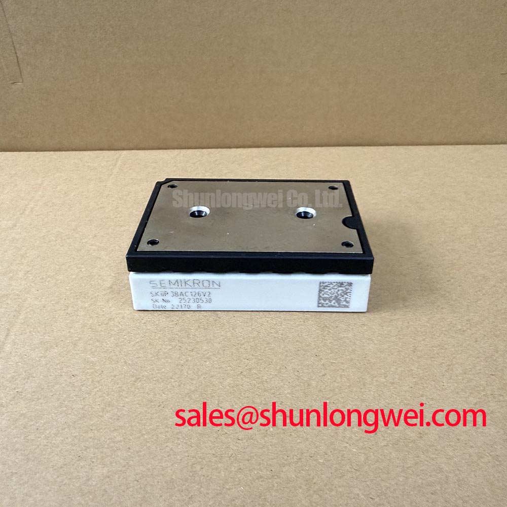
The Semikron SKIIP31NAB12T18 is a Power Integrated Module (PIM) developed to streamline three-phase inverter designs by combining a three-phase input rectifier, a braking chopper, and a three-phase inverter bridge in a single package. Rated at 1200V and 30A, this module leverages solder-free pressure contact technology to improve thermal performance and cycle life. System designers utilize this level of integration to minimize parasitics and reduce assembly complexity. Engineers seeking to prevent solder fatigue choose this pressure-contact layout to eliminate the typical failure modes associated with standard thermal expansion mismatches. For 400V AC industrial motor drives requiring solder-free assembly and low thermal resistance, this 1200V 30A PIM module is the optimal choice.
Key Parameter Overview
Decoding the Specs for Enhanced Thermal Reliability
| Parameter | Value | Engineering Value & Interpretation |
|---|---|---|
| Collector-Emitter Voltage (VCES) | 1200V | Provides excellent electrical safety margins for 400V AC grid operations. |
| Nominal Inverter Current (IC) | 30A (at Theatsink = 80°C) / 45A (at Theatsink = 25°C) | Determines continuous motor load current handling capacity under typical load conditions. |
| Rectifier Peak Reverse Voltage (VRRM) | 1500V | Ensures immunity against line voltage spikes from industrial main lines. |
| Rectifier Output Current (ID) | 35A (at Theatsink = 80°C) | Defines direct current supply limits for the internal inverter stage. |
| Short-Circuit Withstand Time (tsc) | 10 µs (at Tj ≤ 150°C, VGE = 15V) | Allows system microcontrollers to detect faults and trigger safe gate shutdown. |
| Thermal Resistance per IGBT (Rth(j-h)) | 0.7 K/W | Ensures fast thermal transport directly to the heatsink without copper plates. |
| Isolation Voltage (Visol) | 2500V AC (1 minute) | Guarantees electrical safety and isolation compliance for the mounting interface. |
Application Scenarios & Value
Achieving System-Level Benefits in High-Efficiency Motor Control
Engineers designing Variable Frequency Drives (VFDs) for heavy-duty industrial pumps often face the challenge of motor startup surge currents. During initial pump acceleration, the start-up current can peak at several times the nominal rating. Selecting a module like the Semikron SKIIP31NAB12T18 provides a robust 2400 A²s surge energy rating (I²t) in the rectifier bridge, safeguarding the input stage against thermal stress during these demanding startup phases.
Furthermore, this integrated topology is highly effective in applications such as industrial solar inverters, uninterruptible power supply (UPS) systems, and servo drives. By incorporating the rectifier, brake chopper, and inverter into a single block, parasitic loop inductances are minimized, which directly curbs transient voltage spikes during high-speed switching events. When evaluating options across power ranges, designers may note that while this model is ideal for compact mid-power setups, the related SKIIP31NAB12T16 offers alternative layout options, whereas the higher-rated SKIIP32NAB12T49 supports applications with demanding current requirements.
Technical Deep Dive
A Closer Look at the Solder-Free Pressure-Contact Design for Long-Term Reliability
A key feature distinguishing the SKIIP31NAB12T18 from traditional modules is the use of Semikron SKiiP® Technology, which utilizes a pressure-contact system instead of soldered copper baseplates. In standard modules, the mismatch in coefficients of thermal expansion (CTE) between the silicon chip, DBC substrate, and copper baseplate causes mechanical strain during thermal cycling. Over time, this leads to solder joint fatigue, cracking, and eventual thermal runaway. The pressure-contact approach eliminates the baseplate solder layer entirely, relying on direct pressure contacts.
To visualize this, consider how a high-pressure clamp holds mechanical joints tight under shifting loads: similarly, the module's elastic pressure pads maintain uniform contact force, which significantly enhances the overall power cycling capability. To explain how thermal resistance functions in this setup, it acts much like a multi-lane highway during rush hour: reducing the layers (by removing the solder and baseplate) is equivalent to clearing toll booths, allowing the heat flux to flow directly into the heatsink without hitting bottleneck zones.
For design engineers, understanding thermal resistance and thermal design parameters is crucial for reliable operation. The 0.7 K/W thermal resistance (junction-to-heatsink) per IGBT ensures that heat generated during high-frequency switching is efficiently transferred. In high-power designs, managing the gate drive path is equally vital. A gate resistor (Rg) of 39 Ω is typical for managing turn-on and turn-off transitions. Controlling the turn-off dI/dt reduces voltage overshoot, preventing desaturation issues. Additionally, the module's built-in 1000 Ω NTC temperature sensor provides real-time feedback, enabling microcontrollers to implement dynamic thermal throttling before junction temperatures exceed the 150°C maximum threshold.
Frequently Asked Questions
Addressing Common Integration and Design Inquiries
How does the Rth(j-h) of 0.7 K/W directly impact heatsink selection and system thermal design?
A lower thermal resistance of 0.7 K/W per IGBT allows the module to dissipate heat more effectively into the heatsink. This minimizes the temperature delta between the silicon junction and the heatsink surface, allowing engineers to select smaller heatsinks or reduce cooling fan speeds while maintaining safe junction temperatures below 150°C.
What is the primary benefit of the pressure-contact design?
It eliminates solder joint fatigue, significantly boosting thermal cycling lifetime.
Why is the 10 µs short-circuit withstand time (tsc) critical for gate driver design?
The 10 µs limit defines the maximum duration the IGBT can survive a direct short-circuit fault before sustaining thermal destruction. The gate driver must detect this overcurrent state (often via desaturation monitoring) and turn off the gate signal within this window to prevent catastrophic module failure.
How does the rectifier's 1500V peak reverse voltage rating protect the drive system?
An input rectifier rated at 1500V provides a robust safety margin against input line transients and surges commonly found on 400V AC industrial grids, reducing the necessity for oversized external surge protection components.
What is the function of the integrated NTC thermistor?
It provides real-time temperature tracking for active overtemperature protection.
For successful integration of the SKIIP31NAB12T18, engineers should pay close attention to the mechanical mounting torque. The case-to-heatsink mounting torque must be carefully controlled between 2.0 Nm and 2.5 Nm to ensure uniform contact pressure without damaging the internal substrates. Applying a thin, even layer of high-performance thermal paste (typically 20 to 30 microns thick) is highly recommended to fill microscopic air gaps, optimizing the thermal contact interface and ensuring long-term operational reliability.