


Content last revised on October 1, 2026
Preventing Spurious Faults in Four-Quadrant Power Flow with SKHI-24R
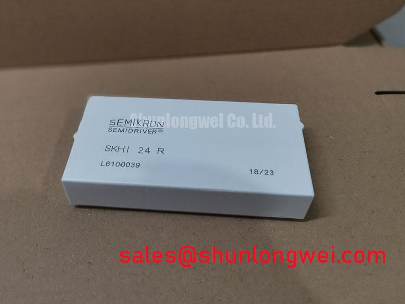
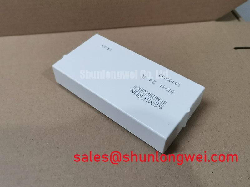
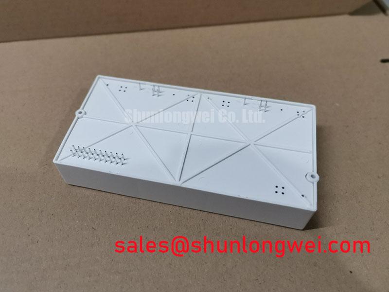
SKHI-24R | Manufacturer: Semikron | Product type: IGBT gate driver. Supply, gate-output and isolation ratings must be checked against the device-specific manufacturer documentation; the supplied product information does not establish numerical ratings or a SEMITRANS power-module package for this part.
Probe the SKHI-24R command input and gate-output path during a controlled transition between battery charging and discharge if an inverter reports a switching fault at power-flow reversal. Compare the timing with a known-good drive path and the controller’s recorded fault sequence. A fault at that transition does not, by itself, establish whether the driver, its supply, the control signal or the power stage is responsible.
In a commercial string inverter or micro-grid energy-storage system, the driver’s role is to translate a control command into a gate signal for the connected power switch. It does not set the system’s four-quadrant capability. That capability depends on the converter topology and its controls. As a Design Consideration, trace the command, driver supply, gate connection and switch-current path on the equipment schematic before attributing a DC-link disturbance to the SKHI-24R.
Peak shaving can repeatedly move power between a battery rack and the inverter link. Inspect logged DC-link voltage and switch-temperature trends alongside the fault timestamp; cyclic loading may expose a marginal connection or cooling interface without identifying a single cause. Where a regenerative braking chopper and resistor are fitted, check their control path separately from the inverter gate drive. The resistor absorbs energy only when its associated circuit is commanded and operating as intended.
Keep driver signal wiring away from high-current switching paths where the equipment layout permits, then verify gate-waveform integrity under representative operation. For power-stage context, compare the actual switch arrangement with documented module families such as SKM200GB12T4; a power module and an SKHI-24R driver perform different functions.
Field Diagnostics: Separating Driver Faults from Power-Stage Mismatch
With power removed and stored energy discharged, compare connector orientation, pin identification and cold-state readings against the equipment schematic and a known-good assembly. A multimeter diode-mode check belongs on an identified power-semiconductor junction, not across unidentified driver pins: protection and control circuitry can make an arbitrary reading misleading. Record test polarity and instrument range so a later technician can reproduce the comparison.
Do not apply an IGBT’s on-state voltage or temperature-dependent current-sharing argument to the SKHI-24R. Those properties concern the connected switches. If parallel power modules are present, compare their gate waveforms, current paths and thermal conditions during commissioning. Static current balance cannot establish dynamic switching balance; differences in wiring or switching timing may only become visible on an oscilloscope.
Inspect the power module’s heatsink joint if faults track load or temperature. Uneven clamping or an unsuitable thermal interface can affect the power stage while the driver continues to receive valid commands. Any interface-layer thickness, fastener torque or tightening sequence must come from the installed module and heatsink instructions, not from the SKHI-24R designation. The Semikron-Danfoss SEMITRANS product information describes a power-module family; it does not establish an SKHI-24R mounting specification.
For a proposed component change, compare functions rather than model-name proximity. SKMD150F12 is a separate power-circuit device to evaluate against the schematic, not a drop-in substitute for a gate driver. Check the driver’s connector, supply arrangement and control interface independently of any rectifier or switch-module decision.
Transient Dynamics: Checking the Gate Return Path
Measure the gate-to-emitter waveform at the connected power switch when an unexplained turn-on indication coincides with switching elsewhere in the bridge. Use probing suitable for the circuit’s potential, and compare the result with the driver input and a known-good switching event. A disturbance at the gate may involve return-path coupling, supply disturbance or the power stage; the waveform comparison helps separate those possibilities.
An auxiliary emitter connection can provide a quieter gate-return reference if the installed power module and driver wiring provide one. Do not infer a Kelvin-emitter terminal from the SKHI-24R model name. As a Design Consideration, follow the equipment schematic to keep the gate-drive return distinct from the main load-current path where that topology supports it, then confirm the resulting gate waveform during switching tests. The manufacturer’s power modules catalog is useful for distinguishing module connection options from driver connections.
Check cable routing, connector seating and continuity before changing gate components. For an inverter under demanding switching conditions, review measured turn-off overshoot alongside DC-link voltage and the connected switch’s documented limits. Unlocking Efficiency in Industrial Drives provides broader switching-technology context, but its device-family discussion cannot supply missing SKHI-24R ratings.
Field Diagnostics: Sizing and Checking the Isolated Driver Supply
Measure the SKHI-24R supply at its connection points during an enable command and again when the reported fault occurs. Compare both readings with the equipment’s documented supply requirements, while checking that the control input remains present. A supply dip and a missing command can produce similar outward symptoms but require different repairs.
For a replacement isolated DC-DC supply, establish the required input range, output arrangement, load demand and isolation requirements from the original driver and equipment documentation. Gate-drive demand changes with the connected switch and operating conditions, so a supply selected only by its nominal output marking is an incomplete match. Isolation withstand and common-mode transient immunity are separate characteristics; neither can be assigned to SKHI-24R from the supplied product information.
If a fault appears only during fast switching, capture the supply and control signals together with the gate waveform using appropriate isolated measurement methods. Inspect the isolator or optocoupler stage specified on the equipment drawing rather than assuming one is built into the driver. Bench Tip: Discharge the DC link and use ESD-safe handling before disconnecting the driver for cold-state pin comparisons. Record the measured condition and the matching schematic node before returning the assembly to service.