Content last revised on October 31, 2026
SK15DGDL12T4ETE1 Assembly Integrity & Layout Architecture: Type-2 Coordination and IGBT Protection
- Isolate the equipment, discharge the DC link, and verify the absence of voltage before probing module connections.
- Compare cold-state collector-emitter and gate-emitter measurements across equivalent circuit positions, accounting for parallel board components.
- Check solder joints, connector seating, heatsink contact, and mounting alignment before attributing a repeated trip to the module.
- Match the complete SK15DGDL12T4ETE1 designation and terminal arrangement to the equipment schematic before replacement.
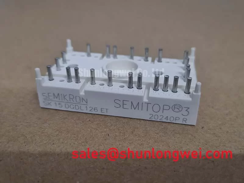
The SK15DGDL12T4ETE1 is a Semikron IGBT module with a SEMITOP® 3 package and an integrated NTC thermistor. Its solderable connections make PCB condition and mechanical support important parts of a replacement assessment, not secondary assembly details.
| Technical specification | Value or rating | Engineering significance |
|---|---|---|
| Collector-emitter voltage | 1200 V — Official Specification | Blocking-voltage reference for assessing measured switching peaks. |
| Nominal collector current | 15 A — Official Specification | Current rating requiring interpretation alongside operating and cooling conditions. |
| Typical collector-emitter saturation voltage | 1.85 V at 25°C — Official Specification | Typical conduction characteristic; consult the datasheet for its complete test conditions. |
| Package | SEMITOP® 3 — Official Specification | Solderable-pin assembly requiring compatible PCB geometry and mounting. |
| Integrated temperature sensor | NTC thermistor — Official Specification | Temperature-dependent input for the equipment’s monitoring circuit. |
Trace the fuse position and fault-current path before selecting a semiconductor protection fuse. As a Design Consideration, total clearing I²t must be evaluated together with prospective fault current, circuit voltage, interruption capability, and the protected assembly’s documented withstand characteristics. Fuse clearing energy alone does not establish IGBT short-circuit survival or guarantee containment of a module failure.
Type-2 coordination describes a tested protective-device and equipment combination under applicable equipment standards; it is not an inherent property of this module. Inspect the DC-link connections for displaced insulation, conductive debris, and unsupported conductors. Preserve the equipment’s specified clearances rather than applying a generic spacing rule to every voltage class and enclosure.
Gate protection needs a separate assessment. As an Engineering Recommendation, keep gate-drive and return paths closely coupled to reduce ringing, then evaluate damping against actual switching waveforms. Check complementary drive timing and fault turn-off behavior: insufficient dead time can permit cross-conduction, while excessive dead time changes output behavior. These settings belong to the validated driver and inverter combination, not a universal replacement-module prescription.
When tracing the wider power circuit, compare the documented function and connections of devices such as SKKR300/0.2-BVR with the equipment schematic. A component elsewhere in the conversion chain is not automatically compatible with this IGBT position.
SK15DGDL12T4ETE1 Circuit Protection & Reliability: Assessing High-Frequency Common-Mode Bearing Current
Compare inverter-output and motor-terminal waveforms when trips or insulation stress appear after a motor-cable change. As a Design Consideration, impedance mismatch on electrically long leads can produce reflected-wave terminal peaks approaching twice the incident voltage under strong positive reflection conditions. This is a transmission-line effect, not a specified SK15DGDL12T4ETE1 output characteristic.
Separate that differential-mode voltage problem from common-mode bearing-current paths. Check cable shield termination, motor-frame bonding, and protective-earth continuity against the equipment design. A differential-mode output filter and a common-mode choke address different mechanisms; selection should account for cable characteristics, switching behavior, motor insulation, losses, and measured results.
Verify module pin mapping against the PCB drawing before attaching probes, and use measurement equipment appropriate to the voltage and common-mode environment. Inspect adjacent conductors for compromised clearance and external busbar hardware for movement without transmitting tightening loads into soldered module pins. The discussion of Stray Inductance, Transient Voltage Overshoot helps distinguish local commutation-loop overshoot from motor-cable reflections.
Application research in IEEE Transactions on Industry Applications provides broader context for drive-system common-mode behavior; it does not establish model-specific filter settings or compliance.
SK15DGDL12T4ETE1 Thermal-Electrical Optimization: Mounting Hardware and Soldered-Pin Integrity
Distinguish heatsink mounting hardware and external terminal blocks from the module’s solderable power connections before adjusting screw engagement. The SEMITOP® 3 package must not be treated as a screw-terminal module with an assumed power-terminal thread depth. Inspect external fasteners for bottoming, incorrect washers, or bracket distortion using the relevant assembly drawing.
Field Alert: Support the PCB and external conductors during assembly so tightening forces do not lever against the module’s soldered pins.
As a Design Consideration, inspect heatsink flatness and interface coverage while avoiding uneven mounting pressure. Check the NTC measurement path through its connector and signal-conditioning circuit before interpreting a temperature alarm as semiconductor overheating. Sensor resistance should be assessed against its documented temperature characteristic, not an arbitrary continuity threshold.
For replacement comparisons, evaluate SKET400/08E by semiconductor function, circuit configuration, drive requirements, and mechanical interface rather than brand similarity; it is not presented here as a substitute. Precision stepper and BLDC servo motion actuators are potential compatibility-assessment contexts only where their power-stage architecture matches this module.
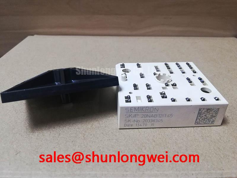
The manufacturer’s SKiiP® Technology reference concerns a separate technology platform, so its construction and assembly practices should not be transferred to this SEMITOP package. Complete the repair by checking solder-joint integrity, unstrained conductor routing, sensor response, and controlled-load thermal behavior.