Content last revised on September 25, 2026
SKKH92/14E Thermal-Electrical Optimization: Gate Trigger Current and Temperature-Dependent Practical Tuning
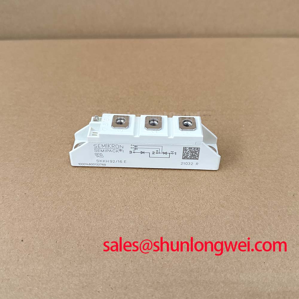
Before energizing the replacement, verify the nameplate against SKKH92/14E, inspect the Semipack housing and terminals for mechanical damage, and perform a documented cold-state terminal check with the module isolated from every external circuit. The recorded identification must match the original equipment documentation, because a thyristor or diode module with a similar outline may have different electrical ratings or internal configuration.
| Manufacturer | Semikron |
| Part number | SKKH92/14E |
| Product category | Thyristor Module |
| Rated voltage | 1400.0 V |
| Rated current | 92.0 A |
| Package | Semipack |
The voltage and current figures above are Official Specification values supplied for this product record. They do not by themselves define the permissible switching frequency, surge duration, cooling arrangement, fuse coordination, or operating point inside a complete power converter. The system engineer must compare the original circuit, load profile, protection network, and thermal path with the applicable Semikron documentation before approving a replacement.
In a field repair, begin at the control interface and confirm that the firing circuit reaches the correct terminals identified in the original equipment wiring. A cold resistance check can help identify an unexpected short, open connection, or wiring mistake, but it cannot prove that the gate trigger circuit will operate correctly under load. Measure the trigger waveform with suitable isolated test equipment and compare it with a known-good channel or the original control documentation.
Gate firing behavior is affected by pulse amplitude, pulse duration, source impedance, wiring inductance, temperature, and the electrical state of the power terminals. The required gate trigger current, gate trigger voltage, latching behavior, and holding behavior must be taken from the applicable manufacturer data for the exact device configuration. Do not transfer trigger values from another Semipack family member solely because the outline appears similar.
For equipment such as a grid-tied static Var compensator or a thyristor-switched capacitor stage, designers should verify firing synchronization across all controlled paths. A single delayed or weak trigger can alter conduction timing and increase current imbalance. Multiple-pulse firing can be evaluated as a Design Consideration where the control architecture supports it, but the pulse sequence, gate-drive isolation, and timing limits remain system-determined.
The thermal inspection should include the mounting surface, insulation arrangement, clamping hardware, and heat-transfer interface. The Semipack package must be installed according to the applicable mechanical instructions, with a uniform thermal interface and even clamping pressure. The module rating of 92.0 A is an official product parameter, not a guarantee that the same current can be carried continuously in every enclosure. Heatsink temperature, airflow, duty cycle, adjacent components, and allowable junction temperature must be verified at system level.
⚠️ Field Alert: Isolate the equipment and wait for the DC-link and capacitor bank to discharge before removing gate or power wiring, then confirm the absence of hazardous voltage with an approved measurement procedure.
When a replacement assessment requires a related high-current module, the SKKT 250/14E may be reviewed as a separate product record; electrical, mechanical, and control compatibility must be checked rather than assumed from the product family name.
Transient Dynamics and Electrical Design: Power Factor and Harmonic Mitigation
In a controlled AC conversion stage, the firing angle changes the interval during which the thyristor path conducts. A field engineer should first confirm the phase reference, gate timing, line sequence, and current transformer polarity before interpreting abnormal reactive power or harmonic measurements. A control timing error can appear as a power factor problem even when the power module itself has no confirmed defect.
The supplied product record identifies SKKH92/14E as a 1400.0 V, 92.0 A Semikron thyristor module in a Semipack package. These are the starting identity parameters for a compatibility review. They do not specify the complete AC-to-DC transfer characteristic of a particular SVC branch or capacitor-switched assembly. The integrator should verify the applied line voltage, commutation conditions, firing-angle range, pulse synchronization, and cooling conditions against the original system design.
For a grid-tied static Var compensator, measure line voltage, branch current, displacement power factor, and harmonic content at the same operating point before and after service. Sweep the commanded firing angle only within the equipment manufacturer’s permitted control range. The often-used angle range from near zero conduction delay toward late firing is a system test condition, not an official rating of this module. Reactive power demand and harmonic performance are governed by the full topology, impedance, control algorithm, capacitor or reactor bank, and grid conditions.
A semiconductor fuse should be selected and coordinated using the applicable fuse manufacturer data and the module’s official surge and thermal specifications. The fuse’s voltage rating, prospective fault current, clearing characteristics, and I2t value must be checked against the actual installation. No fuse coordination value should be inferred from the 92.0 A current figure alone.
The upstream rectification or DC-link arrangement can include complementary power devices outside this product record. Engineers reviewing the front end may also examine the SKKD81/14 as a separate Semikron diode module reference. Its use, rating, and topology position must be validated independently from the SKKH92/14E evaluation.
SKKH92/14E Operational Boundaries: Evaluating Non-Repetitive Surge On-State Current Limits
After a suspected short circuit or capacitor-bank fault, do not reapply voltage immediately after changing the fuse. First inspect the module body, terminal hardware, busbar clearance, gate wiring, heatsink contact, and surrounding insulation. Then test the external circuit for the original fault condition and compare all relevant controlled paths for consistent behavior.
Non-repetitive surge current is a pulse condition with defined waveform, duration, initial junction temperature, and recovery interval. The applicable ITSM value, where provided by the manufacturer, must be read together with its test conditions. It should not be substituted with the continuous current rating of 92.0 A. A ten-millisecond half-cycle test condition may be relevant to a particular datasheet entry, but engineers must verify that the actual fault waveform and starting temperature match the published conditions.
Before reverse voltage is reapplied, confirm that the device has returned to the required blocking state and that the control circuit is not issuing an unintended firing pulse. Oscilloscope measurements should be made with equipment and probes rated for the circuit’s transient environment. If the measured waveform differs from the known-good phase, investigate gate timing, commutation, wiring inductance, fuse operation, and external snubber or MOV networks as possible contributing conditions rather than assigning a single cause without evidence.
A metal-oxide varistor may be used in a system overvoltage network as a Design Consideration, but its voltage rating, energy capability, leakage, ageing behavior, and coordination with fuses and other suppressors are system-level decisions. The SKKH92/14E product record does not establish an independent MOV requirement or a guaranteed clamping level.
For bidirectional DC-DC battery equipment used near an SVC control or energy-storage subsystem, repeated charge and discharge cycles can create thermal cycling in the complete assembly. This observation is an application-level consideration, not field-life data for the module. Confirm the actual temperature profile, current waveform, cooling response, and mechanical stress during qualification testing.
Transient Dynamics and Electrical Design: Short-Circuit Withstand and Fuse Coordination
For a dead-short investigation, disconnect the input source, discharge stored energy, document the fuse condition, and test the semiconductor branch and its surrounding conductors before installing another module. Record terminal discoloration, loose connections, damaged insulation, and evidence of abnormal heating. These observations help separate a power-device fault from a busbar, capacitor, gate-drive, or protection-network problem.
Short-circuit coordination requires comparison of the semiconductor’s published surge withstand data with the fuse’s published clearing I2t under the actual prospective fault current. This is an Engineering Calculation based on manufacturer data, not a value that can be derived from the model number. The calculation must include fuse operating time, available fault energy, circuit inductance, line impedance, initial temperature, and the repetitive fault duty expected by the equipment.
Designers should minimize stray inductance in the high-current loop to control transient voltage during interruption, while keeping gate-control wiring separated from noisy power paths. Any auxiliary or Kelvin-style terminal arrangement must be confirmed from the original module drawing; this product record does not authorize an assumed auxiliary-emitter or auxiliary-cathode connection. The system engineer should verify terminal identity, creepage, clearance, insulation coordination, and probe reference before energizing the repaired assembly.
Thermal interface material should be applied as a consistent, thin layer appropriate to the selected heatsink and mounting method. The correct bolt grade, washer arrangement, clamping sequence, and tightening torque must follow the relevant Semikron mechanical documentation and the equipment manufacturer’s assembly procedure. Excessive pressure, uneven tightening, or a contaminated mounting surface can compromise thermal transfer or mechanical integrity.
For detailed integration work involving gate-drive layout, thermal management, protection, and power-circuit topology, consult the IGBT Design & Integration engineering resource. For product-family context, the manufacturer’s SEMIPACK® Thyristor / Diode Modules information and CAL Diode Technology material should be reviewed alongside the exact device documentation. These references support application assessment, while final acceptance remains dependent on measured system performance and the applicable official specifications.