Content last revised on September 17, 2026
SKKT92/14E Specifications and Application Considerations
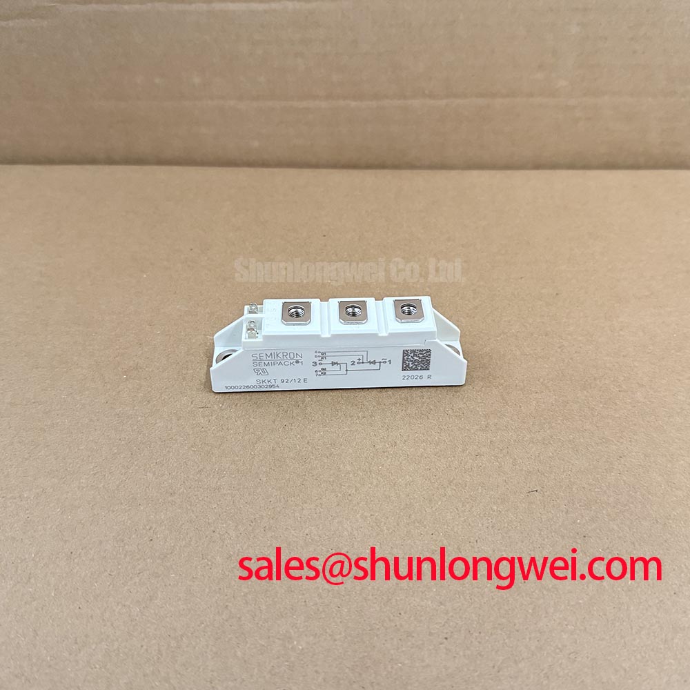
Before installing SKKT92/14E, isolate the rectifier, inspect the case and terminals, and verify the marked electrical ratings against the replacement record for the equipment. This Semikron thyristor/diode module is specified with a Repetitive Peak Reverse Voltage of 1400 V, an Average On-State Current of 95 A at a case temperature of 85°C, and an RMS On-State Current of 150 A. These values provide the starting point for evaluating its suitability in industrial power conversion equipment, including high-current green hydrogen electrolyzer DC power rectifiers.
| Parameter | Official Specification | Engineering Relevance |
|---|---|---|
| Repetitive Peak Reverse Voltage | 1400 V | Defines the repetitive reverse-voltage rating for the thyristor/diode structure. |
| Average On-State Current | 95 A at case temperature of 85°C | Used when assessing continuous current capability together with thermal conditions and load duty. |
| RMS On-State Current | 150 A | Relevant to terminal heating, conduction losses, and interconnect evaluation. |
| Surge On-State Current | 1850 A for 10 ms at a junction temperature of 25°C | Provides the official non-repetitive surge-current reference for short-duration fault analysis. |
| Thermal Resistance, Junction to Case | 0.30 °C/W per thyristor | Used to assess heat transfer from the semiconductor junction through the case and heatsink interface. |
| Isolation Test Voltage | 2500 V RMS for 1 minute | Defines the stated isolation test condition between the active semiconductor terminals and the mounting baseplate. |
| UL Recognition | File E63532 | Provides a component recognition reference for engineers reviewing North American equipment documentation. |
The ratings above are official specification values supplied for this product. Actual operating current, junction temperature, switching duty, cooling performance, fuse coordination, and repetitive surge exposure remain system-dependent. The distributor does not substitute for the original equipment manufacturer’s electrical, thermal, or safety validation.
Assembly Integrity & Layout Architecture: Implementing Junction-to-Heatsink Heat Dissipation for SKKT92/14E
Begin the mechanical inspection with the copper baseplate, mounting surface, terminal threads, and surrounding insulation. The stated Rth(j-c) of 0.30 °C/W per thyristor is meaningful only when the heat path from the case into the heatsink is consistent. A contaminated or uneven mating surface can increase interface thermal resistance and create local temperature differences that are not visible from the average heatsink temperature.
Use the heatsink manufacturer’s specified flatness, surface-finish, fastener, and mounting procedure. The SKKT92/14E documentation available for this page does not establish a universal mounting torque value, so the installer should verify the correct torque from the Semikron mechanical drawing or the equipment service documentation. Tightening must provide uniform contact without bending the module base or stressing the semiconductor housing.
Thermal compound should be applied as a controlled interface layer according to the compound supplier’s application instructions. Excess compound can reduce mechanical stability and contaminate nearby insulation, while insufficient coverage can leave air pockets. After assembly, inspect the interface and confirm that the heatsink is not distorted around the mounting points.
For a green hydrogen electrolyzer rectifier, record the DC load profile rather than evaluating the module only against a nominal current value. The official 95 A average on-state current rating at 85°C case temperature must be considered with airflow, coolant or ambient conditions, bridge configuration, overload duration, and the thermal behavior of adjacent modules. The 150 A RMS on-state current rating is also relevant because terminal and busbar heating can become limiting before the average semiconductor current appears excessive.
Measure case temperature at a repeatable location during commissioning and compare it with the thermal design calculation. If a replacement module runs hotter than the known-good phase under equivalent loading, inspect contact pressure, compound distribution, phase current balance, terminal resistance, and cooling airflow before attributing the difference to the semiconductor itself.
💡 Pro Tip: Disconnect all power sources and wait for the DC link to reach a verified safe state before touching terminals, gate wiring, or the heatsink assembly.
Assembly Integrity & Layout Architecture: Implementing Interphase Transformer Current Balancing for SKKT92/14E
In a six-pulse or twelve-pulse rectifier, current sharing is determined by the transformer arrangement, phase impedance, commutation behavior, busbar geometry, and the control strategy. The SKKT92/14E provides the semiconductor switching element; it does not by itself establish balanced current between bridge sections. Designers should measure each phase and bridge path under the intended electrolyzer load instead of assuming that identical module ratings produce identical current.
For a six-pulse arrangement, verify the phase sequence, transformer secondary connections, bridge polarity, and the firing order used by the controller. For a twelve-pulse system, confirm the phase displacement between transformer secondaries and inspect the interphase transformer connections before energization. A wiring error in either configuration can create abnormal circulating current, uneven thermal loading, or unexpected commutation stress.
The module’s 1400 V repetitive peak reverse-voltage rating should be compared with the measured reverse voltage across the device during switching and line disturbances. This comparison must include transformer leakage inductance, line impedance, commutation notches, and any suppression network fitted by the equipment designer. A nominal 400 V or 480 V AC supply does not remove the need to measure transient conditions at the module terminals.
Keep the high-current path symmetrical where the bridge topology permits it. Busbar length, connection resistance, and magnetic coupling can alter phase current distribution. Gate wiring should be routed away from high-current commutation loops, with the return path treated as part of the gate circuit rather than as an incidental chassis connection. The required gate-drive amplitude, pulse width, trigger current, and repetition pattern must be taken from the applicable Semikron data and the original firing circuit; they should not be inferred from the current rating alone.
The surge specification of 1850 A for 10 ms at a junction temperature of 25°C is an official surge reference, not a continuous operating allowance. When a rectifier supplies a large electrolyzer DC bus, the protection study should distinguish transformer energization, motorized auxiliary loads, capacitor charging, line faults, and true semiconductor short-circuit events. The protection circuit must interrupt the fault within the limits established by the device data and the selected semiconductor fuse.
Where a higher current class is being considered for a revised rectifier, engineers may review the objectively different ratings of SKKT 250/14E. That comparison should cover package compatibility, gate-drive requirements, thermal resistance, terminal arrangement, fuse coordination, and control-board capability rather than relying on current rating alone.
Transient Dynamics & Electrical Design: Gate Trigger Current Dependence on SKKT92/14E
Gate triggering should be checked at the actual temperature and wiring conditions of the rectifier. Gate current can be affected by driver output impedance, cable inductance, connector condition, pulse transformer behavior, and the return path. The supplied product information does not provide a complete gate-trigger-current and gate-trigger-voltage table, so those values must be verified against the applicable Semikron datasheet before commissioning or replacement.
For a high-current rectifier, the firing pulse should reach the gate circuit cleanly and remain within the manufacturer’s specified trigger conditions. Oscilloscope measurements should be taken at the module gate and cathode terminals, not only at the controller output. Compare the pulse shape with a known-good phase while checking for ringing, excessive delay, missing pulses, and a return reference that moves during commutation.
Parasitic inductance in the gate loop can create ringing and reduce the effective trigger current seen by the device. Keep the gate and return conductors close together, minimize unnecessary loop area, and separate gate wiring from the high di/dt anode and cathode paths. Any damping component or gate resistor should be selected as a Design Consideration and validated through measured pulse shape, trigger reliability, and temperature testing rather than copied from an unrelated module.
In systems using multiple firing pulses, the controller should prevent accidental overlap between phases and maintain the timing defined by the bridge design. A dead-time or interlock strategy may be required by the control topology, but the correct timing is system-determined. Engineers should verify commutation overlap, transformer phase displacement, and controller behavior during startup, shutdown, line sag, and recovery from an interrupted firing command.
Negative gate bias is not an automatic requirement for this module based only on the ratings listed above. If the existing equipment uses a negative off-state gate drive, review the complete driver topology, isolation method, gate-cathode voltage limits, and transient response before changing it. The application note Evolution of Negative Off-Bias Gate Drive Circuits can serve as a reference when evaluating that type of circuit architecture.
Long motor or transformer cables can behave as transmission paths and reflect switching disturbances back toward the power stage. This is a system-level issue rather than a standalone module specification. Designers should inspect the measured voltage at the SKKT92/14E terminals, review cable impedance and termination behavior, and validate the peak voltage against the 1400 V repetitive reverse-voltage rating and the complete insulation coordination of the rectifier.
Material and semiconductor technology comparisons should remain separate from the identity of this silicon thyristor/diode module. Background reading on silver sintering and high-temperature die attach and on silicon carbide Schottky diodes may help engineers understand different packaging or rectification approaches, but neither source changes the official ratings of SKKT92/14E.
Assembly Integrity & Layout Architecture: Implementing Semiconductor Protection Fuse Selection for SKKT92/14E
Fuse selection for SKKT92/14E should begin with the bridge topology, prospective short-circuit current, transformer impedance, DC-link capacitance, overload profile, and the semiconductor’s permitted surge and I²t data. The supplied product information confirms an ITSM of 1850 A for 10 ms at 25°C junction temperature, but it does not provide a complete fuse I²t coordination table. Therefore, the fuse clearing I²t, pre-arcing I²t, interrupt rating, voltage class, and physical mounting arrangement must be checked against the official device documentation and the fuse manufacturer’s data.
A semiconductor fuse is selected to limit fault energy before the thyristor or diode is exposed to destructive current. The comparison must use the same fault waveform, duration, temperature basis, and circuit location. A fuse with an apparently suitable nominal current can still be unsuitable if its clearing characteristic allows excessive let-through energy or if its interrupt rating is below the available fault current.
Place the protection device so that the wiring between fuse and semiconductor does not add an uncontrolled fault loop. Inspect busbar joints, laminated connections, terminal washers, and fuse clips for signs of heating or loosening. The module’s 150 A RMS on-state current rating should not be used as a direct fuse-sizing instruction because the correct fuse rating depends on conduction angle, duty cycle, ambient temperature, parallel paths, transformer characteristics, and permissible overload.
During a maintenance replacement, record the installed fuse manufacturer, part number, voltage rating, current rating, and I²t data before fitting a substitute. Verify that the fuse’s physical form and indicator arrangement match the original protection architecture. If the original coordination information is unavailable, the equipment owner should obtain the bridge short-circuit study and perform controlled validation before returning the rectifier to full service.
The 2500 V RMS isolation test rating for 1 minute is an official component test value and should not be treated as a complete system insulation-coordination result. System creepage, clearance, pollution level, transient overvoltage category, enclosure design, and test procedure must be evaluated at equipment level. The UL recognition reference File E63532 can be included in the component documentation package, while final product certification remains the responsibility of the equipment manufacturer.
For any fault investigation, compare all phases using the same measurement points and test conditions. A deviation may indicate a problem in the module, gate circuit, fuse, transformer, busbar, cooling interface, or measurement setup. Confirm the finding with resistance checks, insulation testing appropriate to the equipment, gate-pulse observation, thermal inspection, and controlled load testing before authorizing continued operation.