


Content last revised on October 21, 2026
Assembly Integrity and Layout Architecture for Current Limit and Voltage Ramp Control
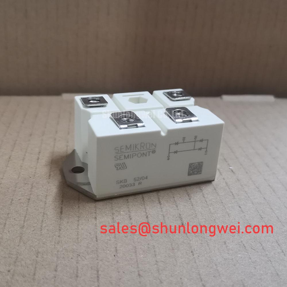
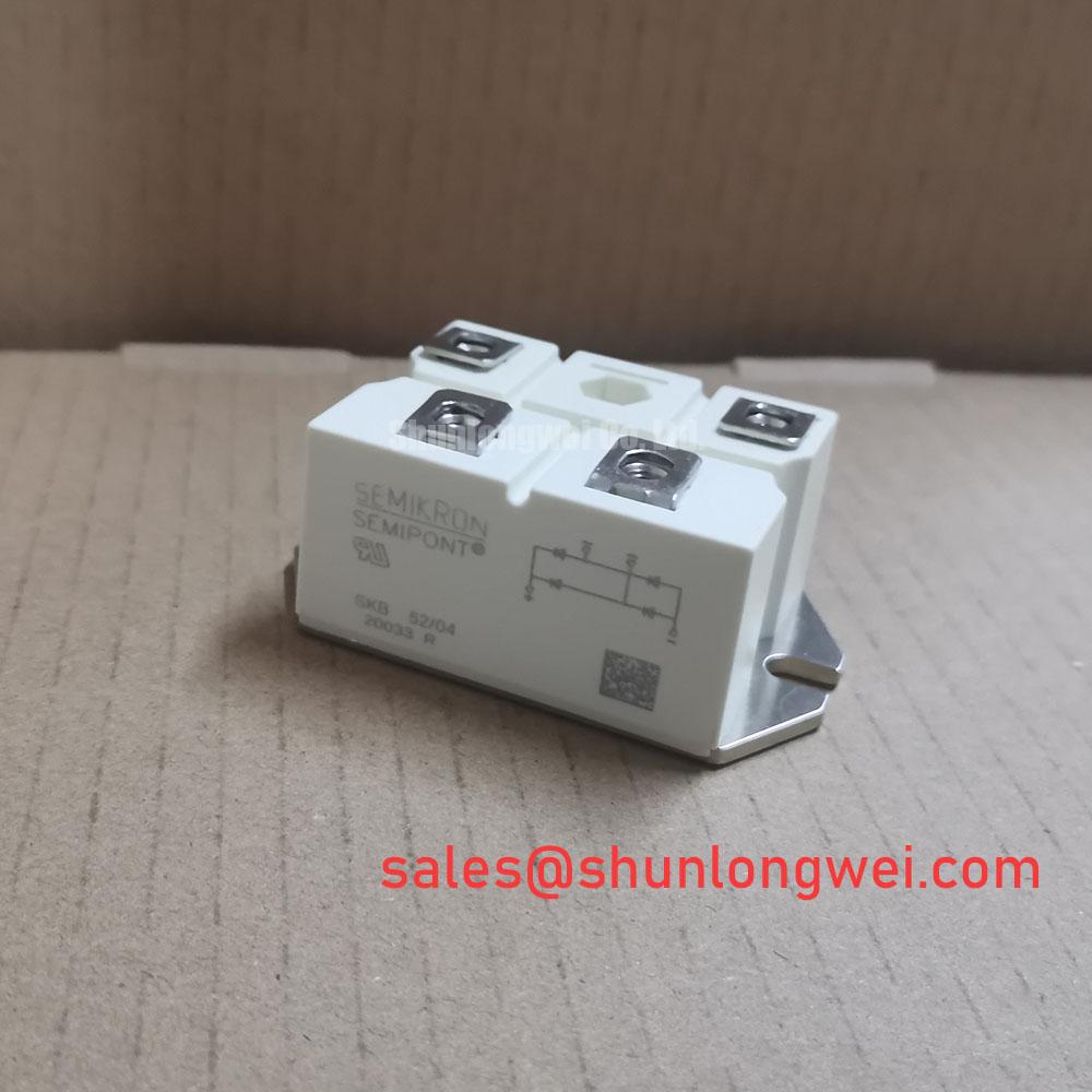
With the soft starter isolated, measure the cold-state resistance paths between the marked power terminals and compare the readings with a known-good unit before applying control power. The SKB-52-04 is a Semikron bridge rectifier module with an official rated current of 52.0 A, a Semipont package, and a working-voltage field identified as Standard Industrial Rating. A numerical voltage value is not included in the supplied specification data, so the original equipment documentation remains the controlling reference for the applied line and DC-link conditions.
In a high-voltage three-phase motor solid-state soft starter, the rectifier stage must be evaluated alongside the selected current-limit strategy. A phase-angle control scheme can reduce locked-rotor inrush from the motor’s uncontrolled starting level toward the system target, while a linear voltage ramp changes the stress profile over the acceleration interval. These are system-control functions, not standalone ratings of the bridge module. The commissioning engineer should correlate firing sequence, motor nameplate current, bypass contactor timing, and semiconductor protection before releasing the starter for service.
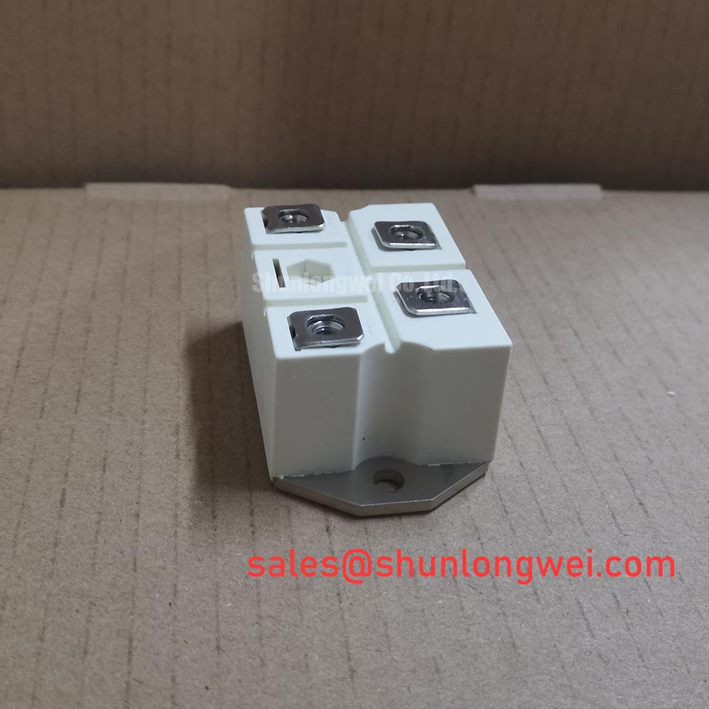
Terminal identification should follow the Semikron connection diagram used for the actual production variant. Check terminal markings, conductor placement, polarity, and the condition of washers and cable lugs before tightening. Mounting pressure should be even across the Semipont base, with the equipment manufacturer’s specified torque taking priority over general mechanical practice. The heat-transfer interface, heatsink flatness, and airflow path should be inspected as an assembly rather than judged from the module body alone.
Fuse coordination belongs in the same review. Select the semiconductor fuse and confirm its I²t coordination against the rectifier’s documented short-circuit protection data and the starter’s prospective fault current. Do not infer fuse suitability from the 52.0 A current label alone; cable impedance, fault clearing time, repetitive starting duty, and enclosure temperature all influence the final protection result.
Operational Boundaries: Diode Reverse Recovery and Commutation Stress
Reverse-recovery behavior should be assessed at the complete commutation network, especially where the bridge feeds a controlled motor-starting circuit or an intermediate DC section. The relevant data items are the manufacturer’s specified peak reverse-recovery current, recovery time, test conditions, repetitive current capability, and junction-temperature limits. These values must be read under their stated test conditions because recovery current and switching loss vary with forward current, temperature, circuit inductance, and applied voltage.
For a service evaluation, capture the current and voltage transitions at the power terminals using suitably rated differential and current probes. Look for excessive commutation overshoot, ringing, or uneven sharing between phases. Such observations can indicate layout inductance, unsuitable snubber selection, gate or firing-control timing interaction, or an incorrectly coordinated upstream protection network; the waveform should be compared with the approved reference design rather than assigned to one component without measurement.
| Parameter | SKB-52-04 | SKD210 reference |
|---|---|---|
| Manufacturer | Semikron | Semikron |
| Product category | Bridge Rectifier Module | Power semiconductor module |
| Rated current | 52.0 A | Consult the applicable product data |
| Package | Semipont | Consult the applicable product data |
| Working-voltage field | Standard Industrial Rating | Consult the applicable product data |
The SKD210 belongs to a different product reference path and should not be treated as a direct electrical replacement for this bridge rectifier without checking topology, terminal assignment, current behavior, voltage class, thermal interface, and protection coordination. The Semikron-Danfoss Power Electronics and Modules official hub provides manufacturer-level product context for engineers reviewing the relevant module family.
💡 Bench Tip: Use ESD protection, discharge the connected capacitors, and establish a cold-state baseline before inserting test probes or reconnecting the control harness.
Circuit Protection and Reliability: Spark Gaps, MOVs, and RC Networks
AC input protection should be coordinated from the expected surge environment, fault current, and insulation system rather than selected from the bridge current rating. For equipment assessed against IEC 61000-4-5 surge conditions, the system designer should define the surge coupling path, protective-device clamping behavior, fuse interruption capability, and the voltage withstand of every connected node. A primary spark gap, where used, requires verified impulse coordination and safe discharge routing; its presence does not establish the module’s own surge rating.
MOV selection should account for the actual line-to-line or line-to-earth connection, continuous operating voltage, surge energy, repetition rate, and failure containment. The MOV, fuse, and enclosure arrangement should be reviewed together so that a degraded suppressor does not create an uncontrolled thermal or fault path. RC snubber stages ahead of controlled junctions can reduce ringing and dv/dt-related disturbance, but their resistance, capacitance, pulse energy, and layout are determined by measured switching behavior and the approved circuit design.
Keep the high-current commutation loop compact and route control wiring away from the power path. Verify terminal creepage, clearance, insulation barriers, and protective-earth bonding against the equipment’s applicable safety requirements. The SKB-52-04 should be installed only after its terminal arrangement, voltage application, fuse coordination, heatsink interface, and surge-protection network have been matched to the original starter design. Engineers reviewing semiconductor protection principles may also consult Wide Bandgap Revolution for broader switching and protection context. In a rectifier and soft-starter power path, the related SKD110/16 may be evaluated as a separate upstream or auxiliary-stage reference, subject to its own electrical and mechanical documentation.
