Content last revised on October 9, 2026
High Voltage Push Pull Row and Column Driver Synchronization and Charge Recovery Resonant Circuitry
| Model | EL4836HB-ICE |
| Manufacturer | Planar |
| Product category | Industrial Grade LCD/HMI Panel |
| Panel technology | Electroluminescent EL Panel |
| Specification status | Decoded Baseline / Standard Form Factor |
| Electrical and optical ratings | Consult the applicable panel and driver documentation before replacement |
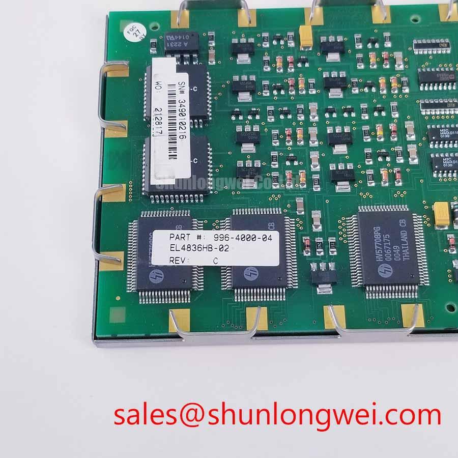
Disconnect the display assembly from its driver before inspecting the row and column interface, then compare the replacement panel’s connector orientation, cable routing, and driver topology with the removed unit. The EL4836HB-ICE is identified as a Planar electroluminescent panel, so its operation depends on the matched high voltage AC excitation and charge recovery arrangement rather than the pixel addressing methods used by conventional TFT LCD modules.
For a railway passenger information system or cab signalling display, the driver must deliver balanced row and column excitation with no unintended net DC bias across the electroluminescent structure. The engineering objective is symmetrical alternating operation, with the commonly evaluated system target of approximately 180 V to 240 V peak treated as a design consideration rather than an assumed standalone rating for this panel. The original driver documentation remains the controlling reference for pulse amplitude, repetition rate, polarity, connector assignment, and insulation spacing.
Charge recovery circuitry should be assessed as part of the complete panel and driver assembly. Resonant recovery can reduce the energy required to reverse the capacitive panel load, but incorrect inductance, damping, switching timing, or cable capacitance can disturb the pulse shape. During service evaluation, compare the recovered waveform at the panel connector with a known-good assembly and look for asymmetric positive and negative excursions, excessive ringing, or a residual offset between successive drive cycles. These observations can indicate a driver mismatch, cable problem, or degraded connection and should be interpreted with the complete circuit diagram.
The most important replacement check is electrical compatibility, not the physical ability to mount the panel in the bezel. Row and column outputs must correspond with the original connector mapping, and the driver must support the panel’s required AC excitation profile. A system integrator evaluating a related display topology may also review the TCG121WXLRFVNN-AN40 as a separate display-system reference, without treating it as an automatic substitute for the Planar panel.
Keep high voltage wiring physically separated from low-level control and communication conductors, and preserve the original shielding, strain relief, and creepage arrangement during reassembly. Cable length changes can alter the resonant response, so the replacement should be tested with the final harness rather than with a short bench lead. When the panel is installed in a cab signalling console or passenger information enclosure, verify the complete assembly during startup, steady display operation, and controlled shutdown.
🔧 Maintenance Note: De-energize the display driver and allow its high voltage storage network to discharge before disconnecting the panel cable.
Luminance Half Life Maintenance without Liquid Crystal Thermal Degradation
Inspect the mounting frame, sealing surfaces, and cable retention before applying power in a cold environment. Because the EL4836HB-ICE is an electroluminescent panel, it does not rely on liquid crystal fluid that can freeze or change viscosity; low-temperature evaluation should instead focus on the panel’s documented response, driver startup behavior, enclosure condensation, and mechanical stress at the interface.
Any reference to a luminance half-life above 50,000 hours should be handled as a documented performance target requiring the applicable Planar specification and operating conditions. Luminance retention depends on drive waveform, duty cycle, ambient temperature, enclosure heat, and display content. Long-term static symbols should therefore be evaluated under the actual operating profile rather than treated as an unconditional field-life guarantee.
The solid-state panel construction can simplify cold-start analysis, but it does not remove the need for condensation control. A display moved from a cold service area into a warmer cabinet may develop moisture on external surfaces, connectors, or internal interfaces. Allow the assembly to reach a stable condition under the equipment manufacturer’s service procedure before energizing it. Check the cabinet air path and gasket contact for dust accumulation, compression loss, or gaps that could expose the panel edge to moisture.
Mechanical installation requires even support around the panel perimeter. Uneven fastener loading can distort the bezel, introduce local pressure points, or produce visible luminance nonuniformity. The mounting frame should constrain the panel without forcing it into a twisted enclosure. In vibration-prone equipment, use the original isolation features and confirm that cable strain is not transferred into the panel connector.
A claimed shock capability such as 100G must be treated as a test-condition value tied to pulse duration, mounting architecture, axis, and qualification method. It should not be converted into a universal installation rating. For field replacement, inspect the supporting structure for loosened fasteners, impact marks, cracked brackets, or displaced cushioning before installing a new panel. The display’s mechanical environment can determine whether a correct electrical replacement remains reliable in service.
Flexible cable handling also deserves attention. Keep the original bend path, avoid sharp folds at the connector exit, and prevent the harness from rubbing against the cabinet during vibration. The connector lock should be fully engaged without forcing the cable into an offset position. If the display remains blank, flickers, or shows incomplete row activation, compare the panel connector seating and driver timing with the known-good signal path before assigning the fault to the panel itself.
For broader reference on display architecture, refresh behavior, and industrial selection factors, see The Ultimate Guide to Industrial TFT LCD Technology. Refresh-rate concepts described for TFT systems should not be transferred directly to an EL panel without checking the relevant driver method. Optical evaluation can also consider the principles described in Display Refresh Rate and Circular Polarizer Anti-Glare Technology, while recognizing that these references do not establish specifications for the Planar model.
When assessing the EL4836HB-ICE for a railway passenger information terminal, cab display, industrial HMI console, or control cabinet interface, confirm the complete mechanical envelope, driver compatibility, connector definition, sealing method, and environmental operating limits as one assembly. A same-size panel with a different electrical technology or connector arrangement may require changes to the driver and enclosure rather than a direct exchange. The TCG057QV1AA-G10 is an example of a separate display product that should be evaluated independently against the original system documentation.