

Content last revised on September 20, 2026
Benchtop Waveform Tuning: Mitigating Stress via Surge Energy Dissipation and Clamping Voltage on SKKD 81/12
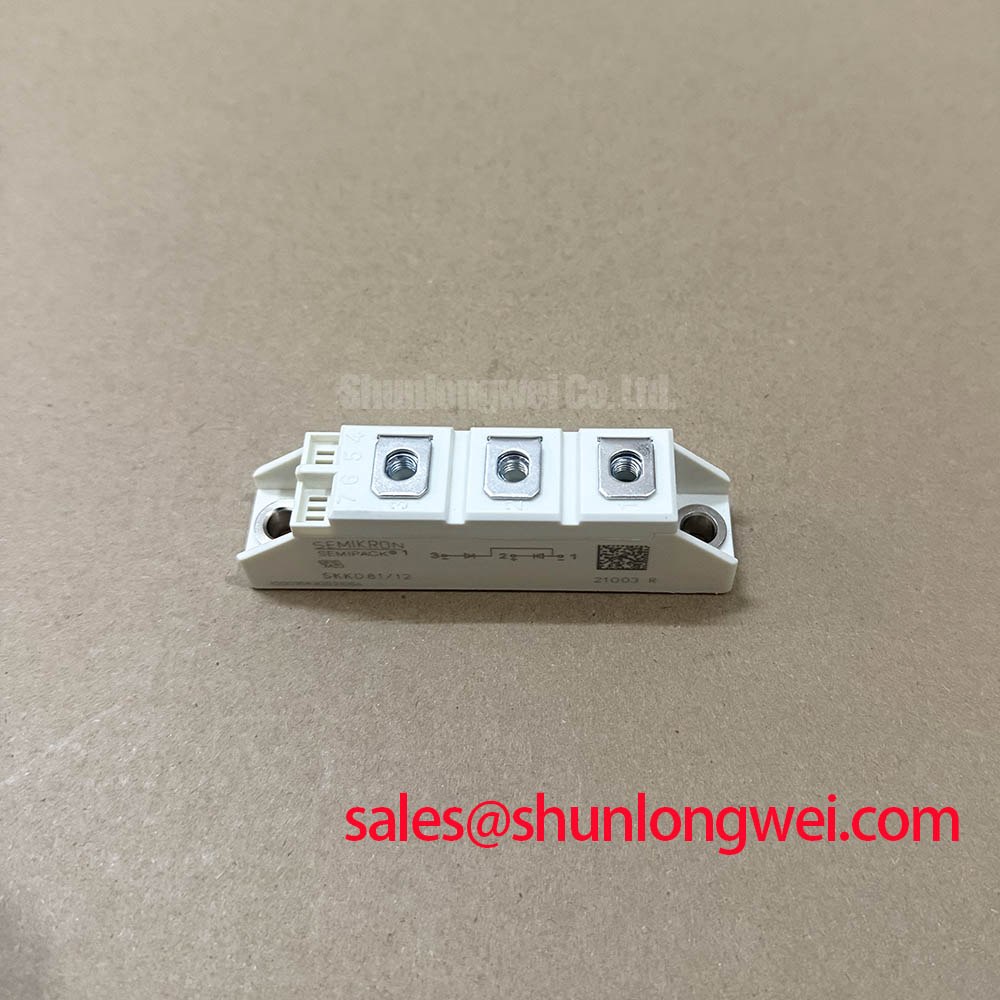
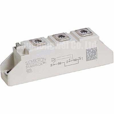
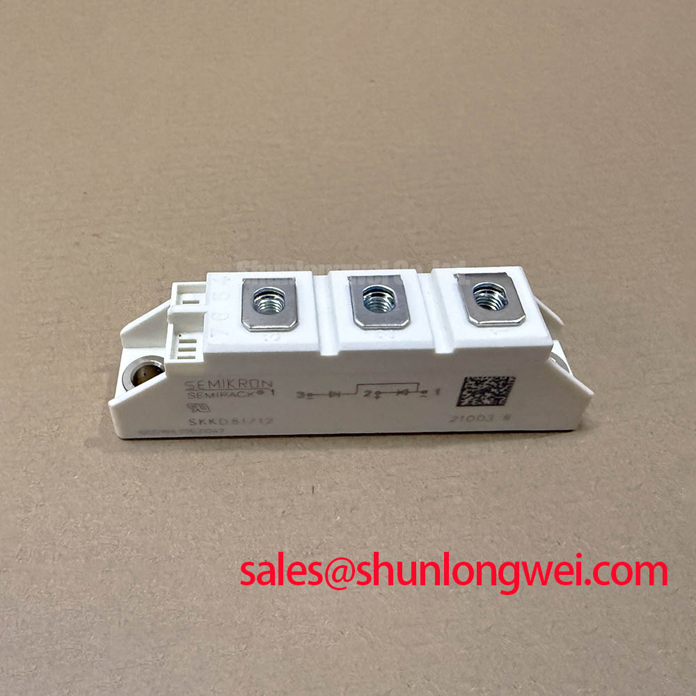
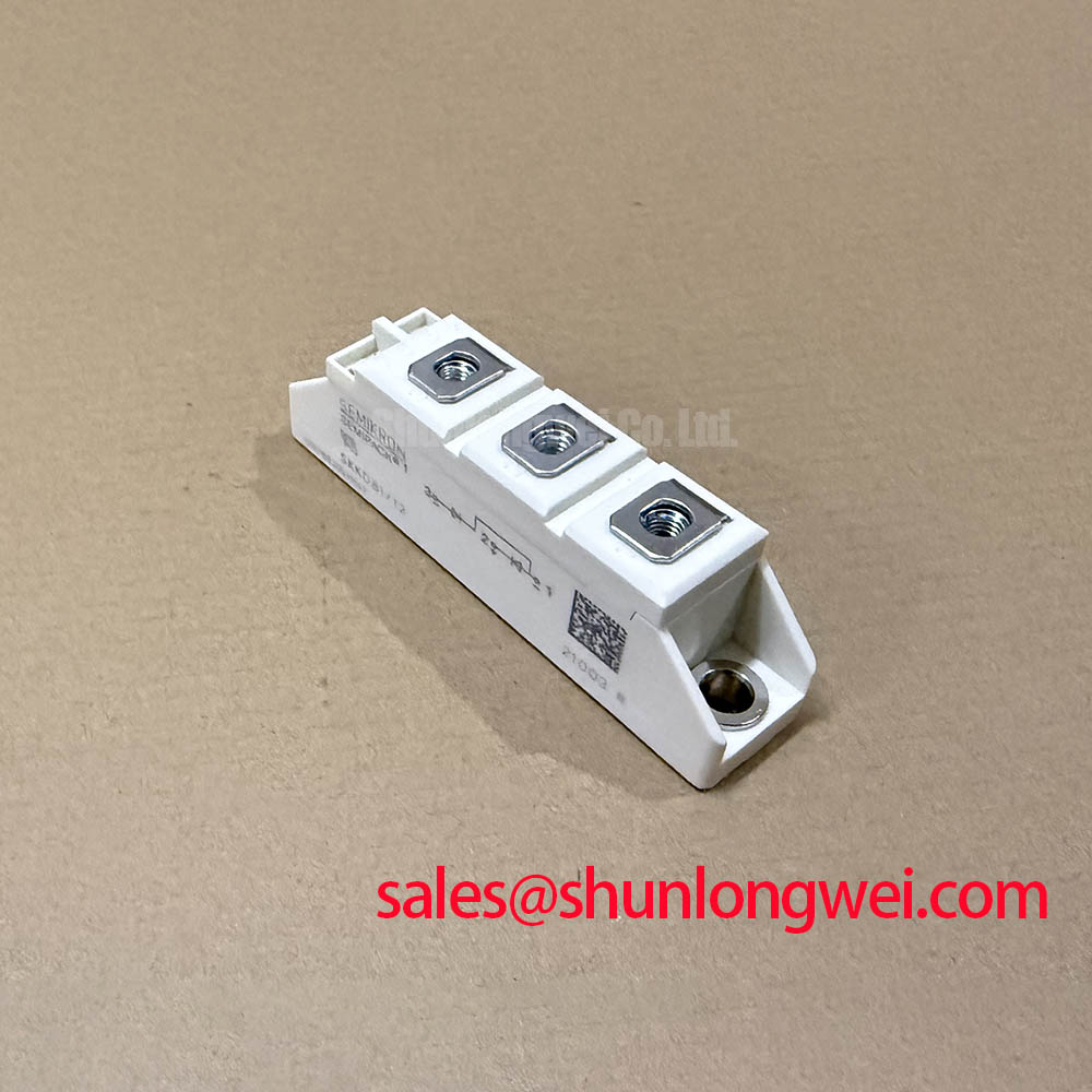
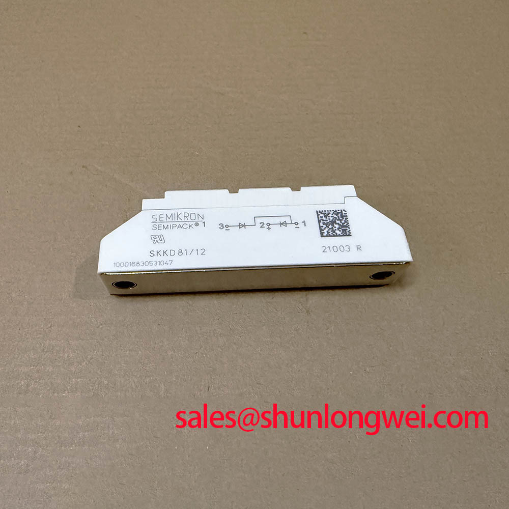
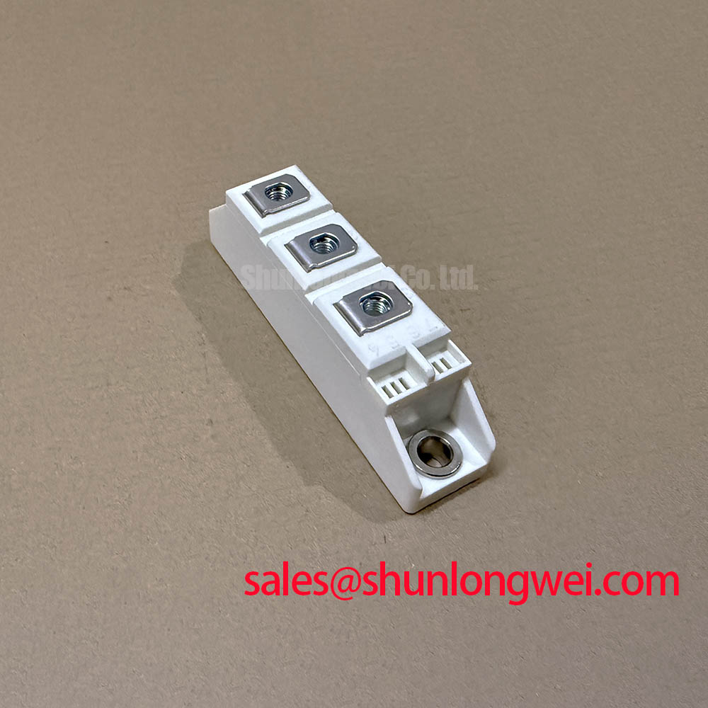
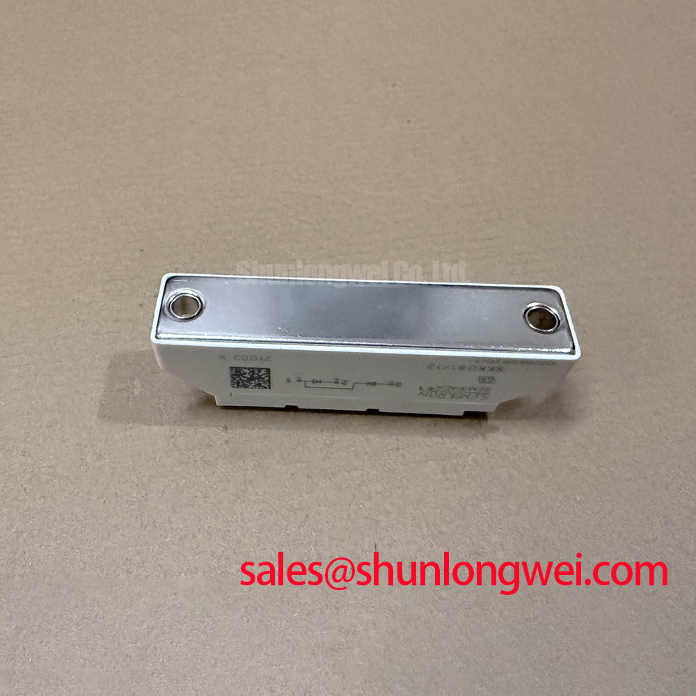
Begin by checking the cabinet nameplate, module marking, terminal hardware, and disconnected cold resistance paths before returning the rectifier assembly to service. The SKKD 81/12 is supplied in a Semipack housing and is identified with a 1200 V voltage rating and 81 A current rating as official specification data provided for this unit.
At the input of a high current power assembly, surge exposure should be assessed at the complete circuit level rather than assigned to the module alone. A Design Consideration is to inspect the existing MOV and RC snubber network for heat discoloration, cracked housings, loose leads, or altered component values. Protective parts ahead of the semiconductor junctions must be matched to the actual supply waveform, conductor routing, switching events, and surge environment verified by the system engineer.
IEC 61000-4-5 is commonly used as a system level reference when evaluating surge immunity. It does not establish an individual module approval or guarantee. During bench work, capture voltage across the installed assembly and inspect the waveform after any snubber or clamping part is replaced. An unexpectedly sharp transient can indicate wiring inductance, degraded suppression parts, poor terminal contact, or a changing load condition.
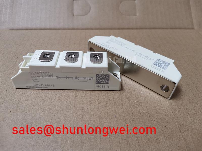
Fuse coordination must be based on the fuse manufacturer documentation and the original module datasheet, including the applicable I²t relationship and fault clearing behavior. No fuse I²t value is stated in the supplied official data for SKKD 81/12. When reviewing adjacent rectifier positions, the SKKD162/12 can be documented as a related module for circuit comparison, while its electrical rating, terminal arrangement, and thermal interface require independent verification.
SKKD 81/12 Thermal Electrical Optimization: Baseplate Thermal Resistance Practical Tuning
Remove accumulated dust from the heatsink fins and confirm that the cooling path is not restricted before attributing elevated cabinet temperature to the module. The Semipack case must sit flat against a clean heatsink surface, with old interface material removed carefully and new thermal compound applied as a controlled thin film. Baseplate flatness, fastening sequence, and contact pressure affect the thermal path from the module to the heatsink.
Thermal resistance from junction to case is a manufacturer datasheet parameter, but no Rth(j c) value is included in the supplied official data for this page. It should therefore be verified from the original Semikron documentation before any temperature rise calculation or heatsink decision is made. Semikron identifies its SEMIPACK thyristor and diode module family as a power module product line; the exact SKKD 81/12 variant documentation remains the controlling source for its mounting and thermal limits.
Use the prescribed torque and terminal tightening instructions from the applicable manufacturer drawing rather than applying a generic torque value. Over tightening can distort the package or damage threads, while inadequate tightening raises contact resistance. ⚠️ Maintenance Note: Monitor terminal and heatsink contact temperature during loaded operation, then inspect airflow and fastening condition when a localized rise is observed.
For medium frequency induction melting or hardening furnace power supplies, engineers should evaluate cooling capacity against the measured duty cycle, enclosure temperature, and process load. Condensation control also matters after shutdowns or rapid ambient temperature changes; inspect for moisture traces before energizing high current sections.
SKKD 81/12 Operational Boundaries: Evaluating Thermal Avalanche Margins during High Peak Limits
Confirm that applicable repetitive peak and transient voltages remain within the specified 1200 V device voltage rating, and assess current demand against the stated 81 A rating under the applicable manufacturer conditions. These values alone do not define repetitive overload capability, half cycle surge withstand, permissible junction temperature, or fault duration. Those boundaries need the original datasheet values and the measured operating waveform.
The requested evaluation of sinusoidal 10 ms half cycle surge behavior requires the official IFSM rating and specified test conditions. Neither is available in the supplied parameter set, so no numerical surge conclusion should be drawn for this page. As a Design Consideration, record the incoming current waveform during startup, transformer energization, load changes, and fault recovery. Compare the observed peaks with the applicable manufacturer limits before allowing repeated operation.
“Thermal avalanche margin” should not be assumed for this diode module from nominal voltage and current markings alone. A transient after reverse voltage reapplies can be affected by commutation conditions, source impedance, cable routing, snubber condition, and temperature. Engineers should verify voltage recovery on an isolated measurement setup and review the commutation circuitry where relevant.
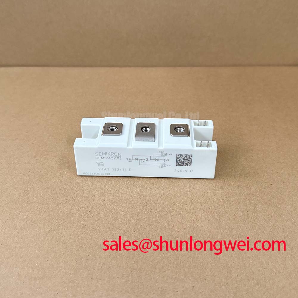
When a hardware replacement assessment is necessary, SKKT273/12E is a separately identified module that can be reviewed against the original assembly. It must not be treated as a direct interchange without confirming circuit function, voltage class, current capability, mounting pattern, terminals, and cooling requirements.
Assembly Integrity & Layout Architecture: Implementing Reverse Recovery Charge Temperature Coefficient for SKKD 81/12
Inspect busbar alignment before tightening terminals. A busbar that pulls sideways on the module connection can create persistent mechanical stress and unstable electrical contact. Keep high current paths compact and avoid unnecessary loop area where commutation transients must be controlled. This is an Engineering Recommendation intended to suppress inductive overshoot, with final performance verified by switching tests in the actual equipment.
Reverse recovery behavior is described by parameters such as peak recovery current and recovery time, but no Irrm, trr, recovery charge, or temperature coefficient is contained in the supplied official data. The original product documentation should be consulted before predicting commutation loss, selecting snubber components, or setting an EMI mitigation target. A change in waveform ringing may indicate altered recovery behavior, but it can also arise from layout changes, poor probing practice, loose connections, or a changed source condition.
For fault finding in induction heating power sections, isolate the affected circuit, inspect the suppression network, verify terminal continuity, and compare captured waveforms with a known healthy channel when available. The technical context in Resonant Topologies in Home Appliances can help distinguish topology level commutation behavior from a module level concern. Final acceptance should be based on verified circuit operation within the documented electrical and thermal boundaries of the installed SKKD 81/12.