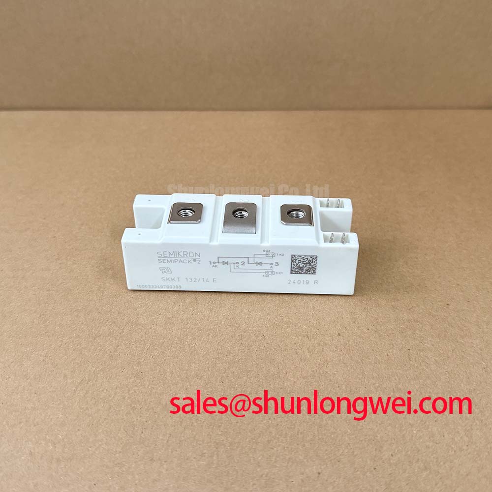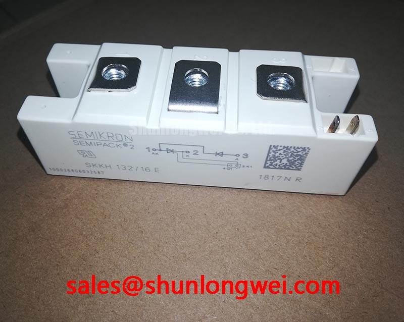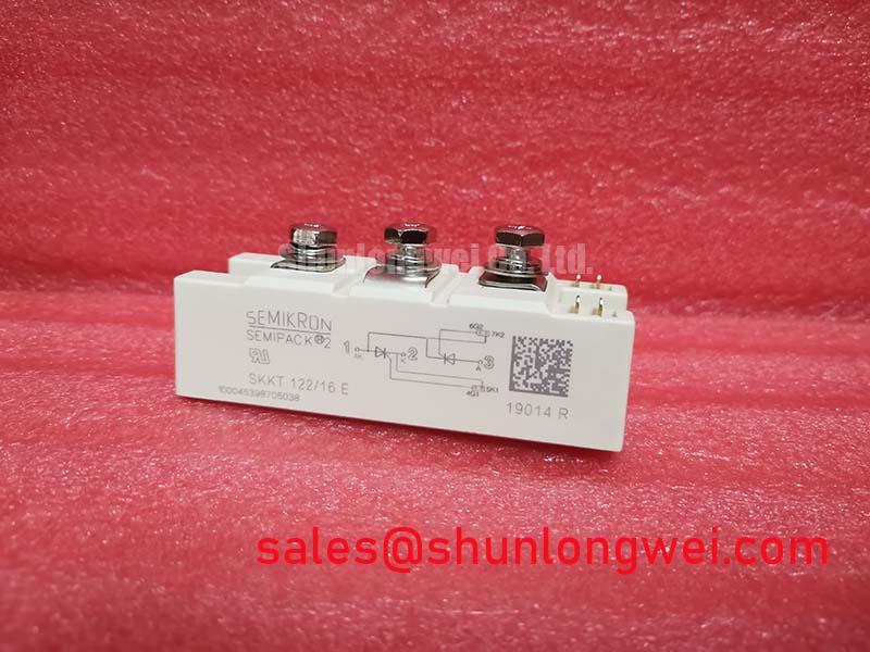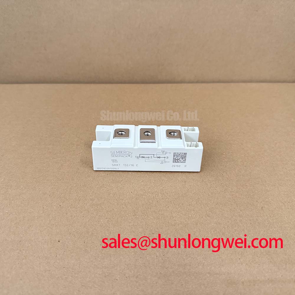




Content last revised on September 15, 2026
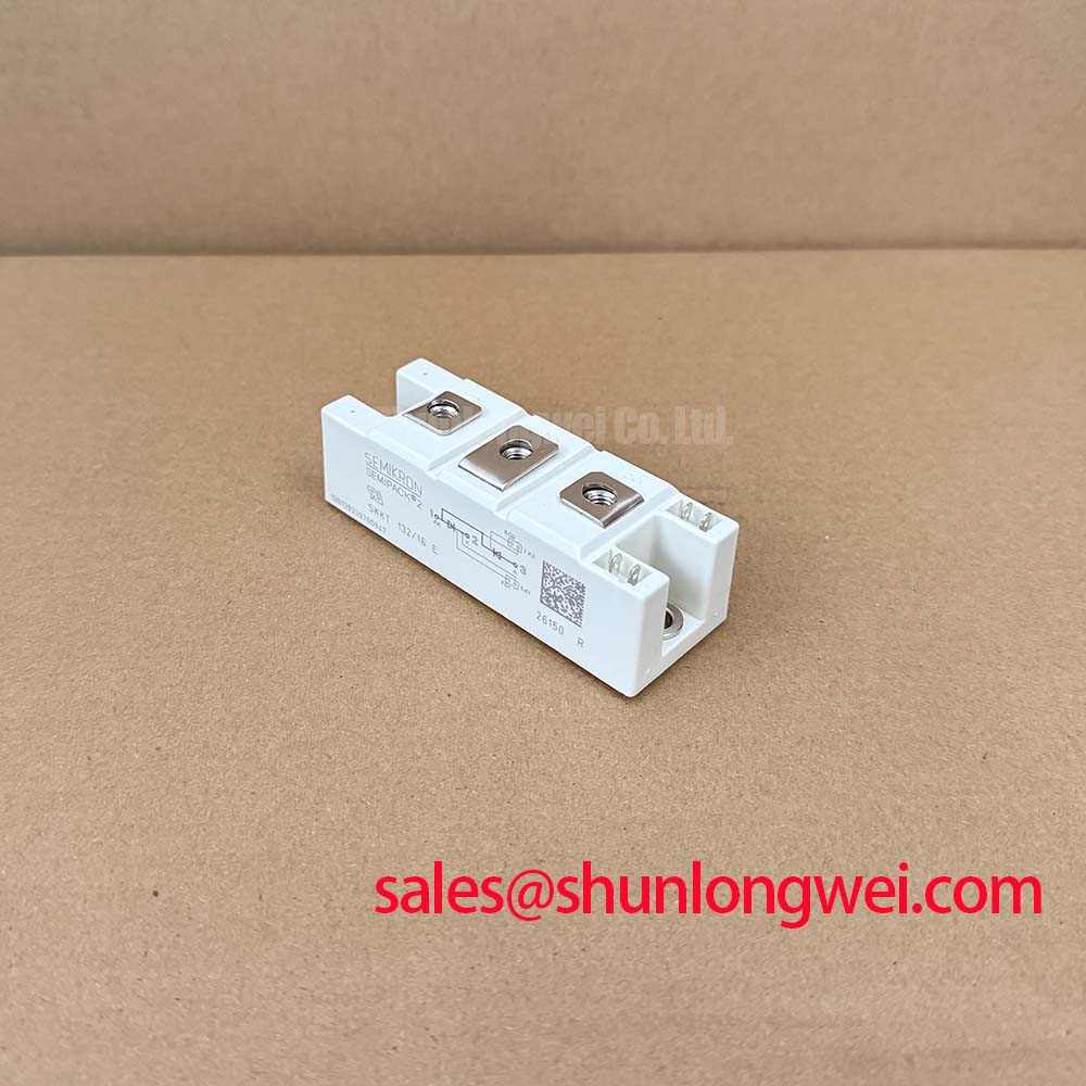
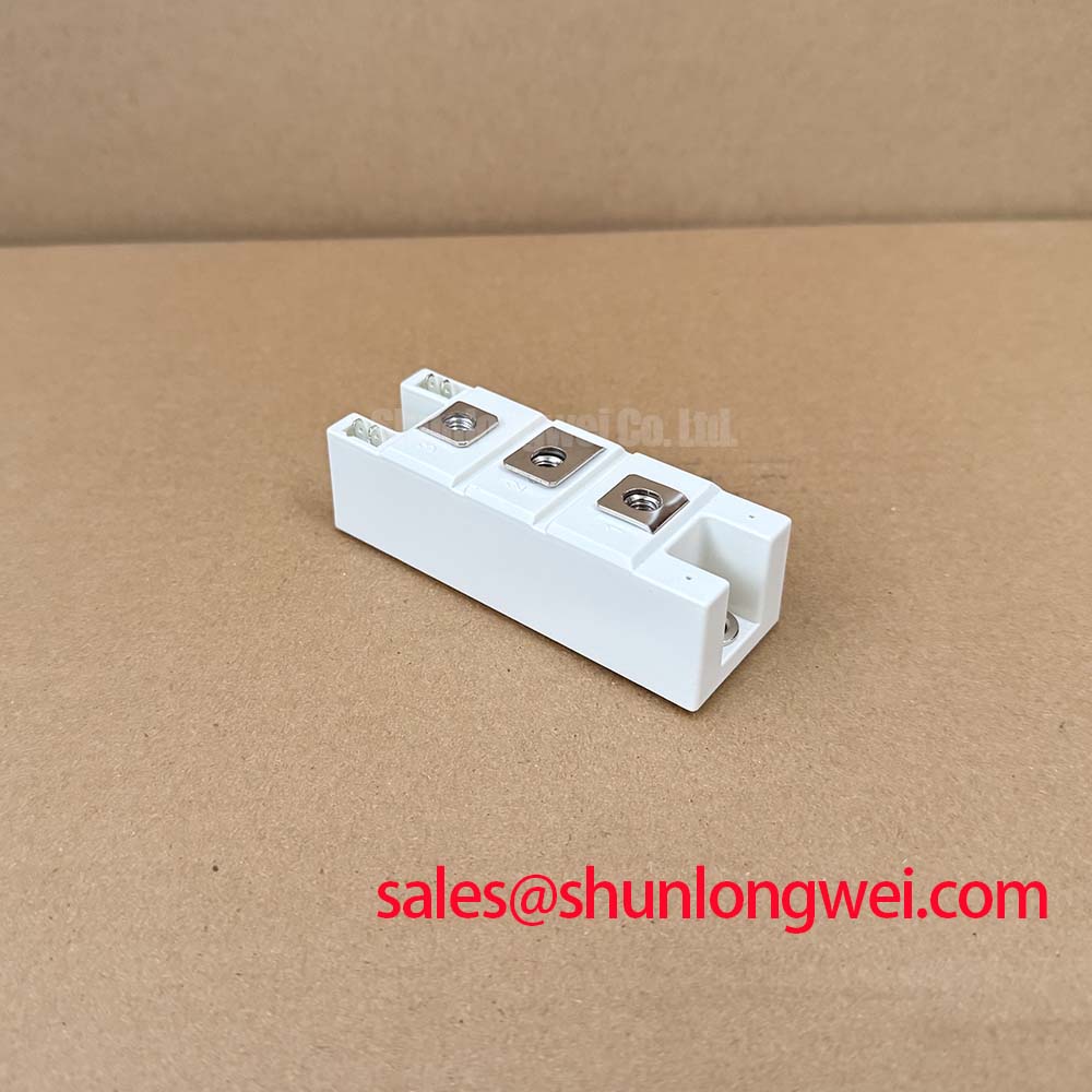
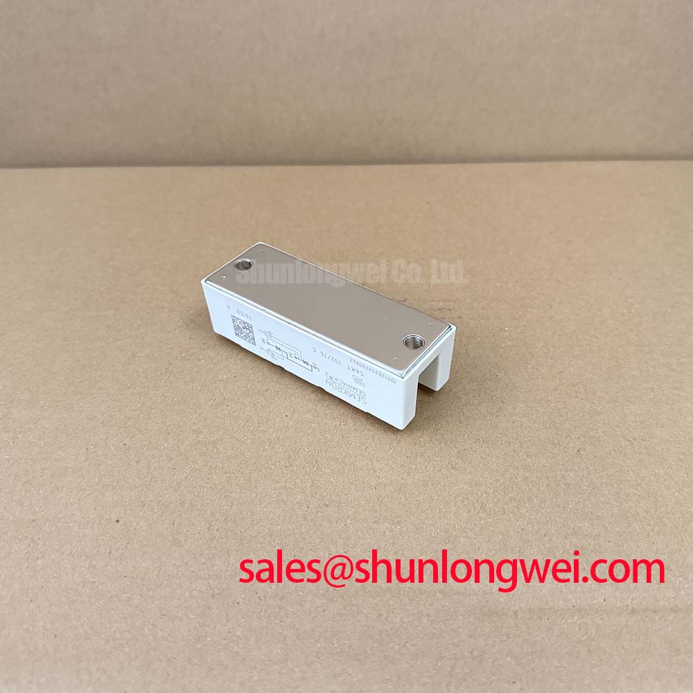
SKKT132/16E Specifications and Installation Scope
With the power cabinet isolated and discharged, first verify the nameplate boundary of the SKKT132/16E against the replacement record, then inspect the heatsink contact face, cable lugs, and gate connections for heat discoloration, looseness, or moisture residue before installation. This Semikron dual-thyristor module is officially specified with VRRM 1600 V, IT(AV) 137 A at TC = 85°C, and ITRMS 220 A. These ratings define the electrical identity of the module; the surrounding commutation network, fuse coordination, cooling path, and firing circuit remain system-determined.
| Official Datasheet Specification | Value |
|---|---|
| Repetitive peak reverse voltage, VRRM | 1600 V |
| Average on-state current, IT(AV), TC = 85°C | 137 A |
| RMS on-state current, ITRMS | 220 A |
| Surge on-state current, ITSM, 10 ms, Tvj = 125°C | 4000 A |
| Maximum forward voltage, VT, IT = 300 A | 1.8 V |
| Critical off-state voltage rise, dv/dt | 1000 V/µs |
| Junction-to-case thermal resistance, per thyristor, Rth(j-c) | 0.19 °C/W |
| Isolation voltage, AC for 1 minute, Visol | 3000 V |
Preventing Spurious Faults: Minimizing Commutation Turn-Off Voltage Spikes for SKKT132/16E
In a phase-controlled power section, unwanted turn-off voltage peaks are best investigated at the commutation path rather than attributed to the thyristor alone. The 1000 V/µs critical dv/dt rating is an Official Datasheet Specification and should be checked against captured waveforms under the actual load, firing angle, supply condition, and temperature. A rising off-state voltage can couple into a sensitive gate circuit, while reverse-recovery behavior in the commutating diode path can increase transient current and radiated noise.
Design Consideration: assess the reverse-recovery peak current and recovery softness of the diode used in the commutation loop from its own manufacturer documentation. Those values are not specified for the SKKT132/16E and should not be assumed. Keep gate-return conductors and high-current commutation conductors arranged to minimize shared impedance, then validate the result with an appropriately rated differential voltage probe and current measurement. If the installation includes a rectifier stage such as the SKKD162/12, its recovery and wiring loop behavior should be evaluated as part of the same power-path review.
⚠️ Maintenance Note: Periodically monitor terminal and heatsink contact temperature rise under stable load, clear blocked airflow, and recheck terminal tightening during planned maintenance with the equipment manufacturer’s specified torque.
Assembly Integrity & Layout Architecture: Implementing Fuse Total Clearing I2t versus Device Melt for SKKT132/16E
The official surge capability of 4000 A for 10 ms at Tvj = 125°C is useful for defining a short-duration fault withstand boundary, but it is not a substitute for semiconductor-fuse coordination. A fuse selection review must compare the fuse manufacturer’s pre-arcing and total-clearing I²t data with the device and circuit fault-energy limits documented for the complete assembly. Total clearing behavior includes the energy released after the fuse element begins to melt, so using a nominal current rating alone is insufficient for dead-short analysis.
Engineering Recommendation: obtain the fuse coordination table applicable to the exact topology, prospective fault current, and operating voltage. Confirm that the protective device opens before excessive energy reaches the semiconductor and bus structure, while also verifying that normal overloads, transformer inrush, or load transients do not create nuisance interruptions. The SKKT132/16E 220 A RMS rating should be interpreted with its thermal conditions and waveform duty, rather than treated as a universal continuous system-current allowance.
Terminal stack-up deserves equal attention. Use clean, flat lugs with no trapped insulation, avoid placing mechanical stress into the module terminals, and check that parallel current paths have comparable conductor geometry. Where a higher-current Semikron family unit is being assessed for a documented equipment redesign, the SKKT 250/14E can be reviewed objectively against the original circuit voltage, current, cooling, mechanical interface, firing arrangement, and protection coordination. It is not an automatic replacement for the SKKT132/16E.
Benchtop Waveform Tuning: Mitigating Stress via Baseplate Thermal Resistance on SKKT132/16E
Before energizing a repaired power assembly, inspect the heatsink for flatness, corrosion, embedded debris, and blocked cooling channels. The SKKT132/16E has an Official Datasheet Specification of Rth(j-c) 0.19 °C/W per thyristor. This value describes the junction-to-case path under specified conditions; it does not include the thermal interface material, heatsink, fan performance, cabinet air temperature, or contamination accumulated in service.
Design Consideration: apply thermal compound as a continuous thin interface layer in accordance with the system assembly procedure, then tighten the module in a controlled sequence to promote even contact pressure without distorting the package. After commissioning, compare temperatures across the mounting region and inspect for uneven compound spread during scheduled shutdowns. A localized hot region may involve poor surface contact, airflow reduction, unbalanced current sharing, or changed load conditions and should be investigated with electrical and thermal evidence.
For background on power-switching device behavior in three-phase conversion, including the different engineering considerations applied to modern silicon-carbide MOSFET systems, consult The 1200 V CoolSiC™ MOSFET Advantage in Three. That technical context should not be used to transfer MOSFET gate-drive assumptions to this thyristor module.
SKKT132/16E Operational Boundaries: Evaluating RC Snubber Network Optimization to Prevent Limits
An RC snubber is evaluated from measured circuit behavior, not selected from a generic value. Its role is to control voltage rate of rise and switching overshoot across the relevant commutation path. For the SKKT132/16E, designers should verify peak blocking voltage against the 1600 V VRRM rating and evaluate the observed dv/dt against the official 1000 V/µs limit during representative switching tests. Snubber resistor pulse capability, capacitor AC stress capability, and the layout of their connections are all part of that validation.
Where rapid current transfer creates undesirable transient behavior, a series saturable reactor can be considered as a Design Consideration. Its suitability depends on the load, commutation sequence, current waveform, and protection strategy, so its characteristics must be confirmed through system testing. Minimize parasitic loop inductance between the module, snubber, DC source, and commutating components to suppress turn-off inductive overshoots, then verify voltage margins with captured waveforms.
The module’s 3000 V AC isolation voltage for 1 minute is an Official Datasheet Specification for the stated test condition. It does not establish complete equipment insulation coordination, enclosure protection, or EMC compliance. For product-family context, Semikron-Danfoss provides technical information on SEMIPACK® thyristor and diode modules and CAL diode technology. When evaluating this module for a medium-frequency induction melting or hardening furnace, confirm firing synchronization, cooling capacity, protection coordination, and measured switching stress in the original power-supply topology.