

Content last revised on October 3, 2026
SKKT 132/16 Operational Boundaries: Fuse Coordination During a Dead Short
| Model | SKKT 132/16 |
|---|---|
| Manufacturer | Semikron |
| Product category | Thyristor module |
| Package | Semipack |
| Rated voltage | 1600 V |
| Rated current | 132 A |
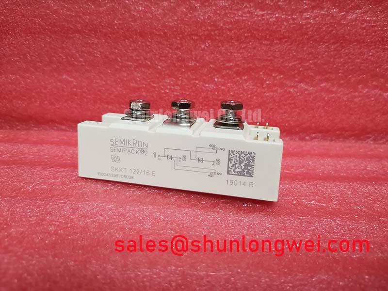
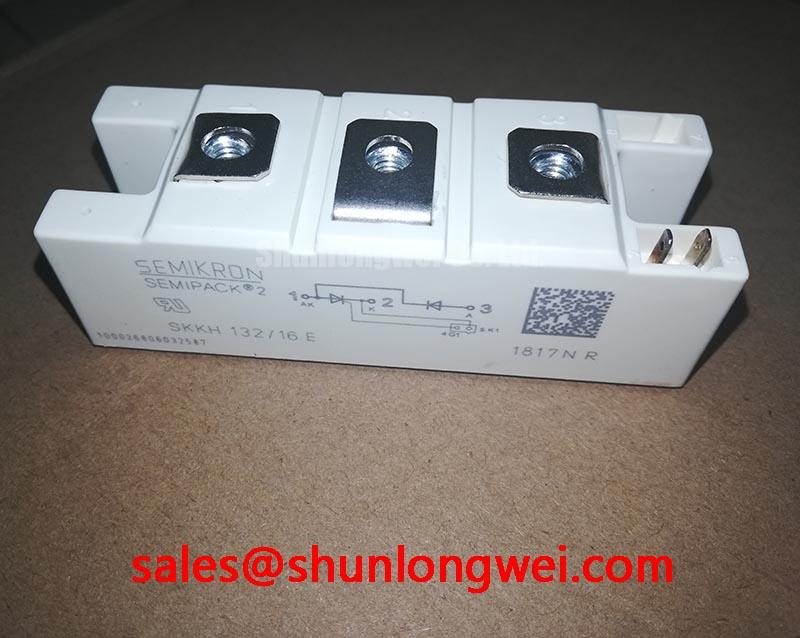
Measure for an unintended short across the main terminals with the equipment isolated and the DC link discharged. A low resistance reading warrants checking the surrounding buswork and other power devices before attributing the fault to the SKKT 132/16. Record the terminal connections as found; the firing circuit and load path must agree with the equipment schematic before power is restored.
The stated 1600 V and 132 A ratings are device specifications, not short circuit withstand ratings. For a proposed semiconductor fuse, compare its total clearing I²t at the applicable prospective fault current with the module’s specified nonrepetitive surge and I²t limits at the relevant starting junction temperature. That comparison also depends on the available supply fault current and the complete protection path. Without those device limits and fuse data, type 2 coordination and damage containment cannot be established.
When assessing a replacement, compare the circuit arrangement, gate and main terminal positions, mounting footprint, voltage class, current rating and surge data rather than matching a package name alone. SKKT91/08D is a separate model to evaluate against those requirements, not a confirmed drop in replacement. In a furnace supply, the rectifier and controlled power stages must also be traced as a system; SKKH273/18E is an example of another module whose role depends on the actual circuit topology.
SKKT 132/16 Operational Boundaries: Gate Triggering Across Temperature
Probe the gate to cathode waveform at the module terminals while checking an intermittent firing complaint. Comparing the affected position with a known working position can expose differences in pulse arrival, polarity or wiring impedance that are hidden at the controller output. Keep the measurement referenced to the correct cathode terminal and follow the equipment’s isolation procedures.
Gate trigger current, trigger voltage and latching behavior vary with operating conditions. The driver therefore needs assessment at the cold and hot limits of the intended equipment, using the device’s gate characteristic limits and the measured anode current rise. Pulse rise, pulse duration, any sustaining portion and any repeated firing pulses should be judged against the actual conduction interval. A specific gate current slew threshold or back porch value cannot be assigned to SKKT 132/16 from its voltage and current ratings alone.
As a Design Consideration, keep the gate and cathode return path compact where practical to limit coupled noise, then verify triggering at the module terminals under representative load conditions. A missed firing event can arise from the driver, its connections or the surrounding circuit; the waveform comparison helps separate those possibilities without presuming a single cause.
SKKT 132/16 Transient Dynamics: Surge Protection in the Power Path
Capture the voltage across the module during switching when unexplained trips coincide with supply disturbances. Compare the observed peak and ringing with the stated 1600 V rating, while accounting for the measurement probe and its connection. The rated voltage is a device boundary, not evidence that the assembled equipment meets a surge immunity requirement.
IEC 61000-4-5 addresses surge immunity testing at equipment ports. It does not certify a thyristor module on its own. For an industrial AC input, designers should evaluate surge protection placement, earthing and coordination with upstream protection using the equipment test requirement. MOV selection depends on the continuous operating voltage and expected surge duty; an RC snubber must be assessed for its effect on device voltage and current during the actual switching sequence. Neither network can be sized responsibly from the module’s nominal ratings alone.
For an induction melting or hardening furnace supply being considered for this module, trace the input protection, controlled rectifier, DC link and load stage before changing suppression components. This is a Design Consideration, not a statement of application approval. The Semikron Danfoss SEMIPACK thyristor and diode module range provides manufacturer context for the package family; system surge performance still requires testing of the assembled equipment.
SKKT 132/16 Assembly Integrity: Thermal Contact and Terminal Layout
Inspect the heatsink contact pattern when one module runs hotter than comparable positions at similar current. Remove old interface material, check the mating surfaces for damage and assess whether mounting pressure has been applied evenly. A fresh, uniform thermal interface should fill surface irregularities without preventing firm contact; its application and mounting torque must follow the applicable module and heatsink documentation rather than an assumed value.
The supplied product facts identify a Semipack enclosure but do not specify junction to case thermal resistance, baseplate construction or fastening torque. Treat each as an item requiring the exact device documentation and installation conditions. During operation, compare case or heatsink temperature readings at repeatable measurement points and review current sharing with adjacent paths. Uneven heating may reflect contact, airflow, terminal resistance or unequal electrical loading, so temperature alone does not identify the fault.
Bench diagnostic: Disconnect and discharge the power circuit before loosening a main terminal or gate lead. As a Design Consideration, route power conductors to limit unwanted loop inductance and check terminal joints for consistent contact; verify switching voltage peaks under representative conditions rather than assigning a fixed layout limit. Further gate drive and thermal integration principles are discussed in IGBT Design & Integration, with its IGBT specific guidance kept distinct from this thyristor module’s requirements.