Content last revised on September 14, 2026
SKKH273/18E Installation and Official Specifications
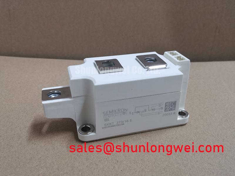
With the rectifier cabinet isolated and discharged, first verify that the installed module marking, terminal layout, heatsink contact face, and insulation hardware correspond to the original assembly before applying a meter across any power terminals. The SKKH273/18E is a Semikron thyristor-diode module in the SEMIPACK 3 housing, rated at 1800 V repetitive peak reverse and off-state voltage and 274 A average on-state current per thyristor at a case temperature of 85°C, according to the official datasheet specification. Its housing envelope is 115 × 50 × 52 mm, making the original mechanical footprint and terminal orientation central checks during a repair.
The official non-repetitive surge rating is 9000 A for a 10 ms event at a junction temperature of 25°C. The associated official I²t rating of 405000 A²s, measured under the same condition, is relevant when reviewing semiconductor fuse coordination after an AC-side fault. The module also has an official junction-to-case thermal resistance of 0.104 K/W per chip under continuous conditions and a 3600 V AC for 1 second isolation rating between terminals and baseplate.
| Official specification | Value | Integration relevance |
|---|---|---|
| Repetitive peak voltage | 1800 V | Reverse and off-state voltage boundary |
| Average on-state current | 274 A per thyristor at Tc = 85°C | Continuous current reference |
| Surge current | 9000 A at Tj = 25°C, 10 ms | Non-repetitive fault and inrush assessment |
| I²t | 405000 A²s at Tj = 25°C, 10 ms | Fuse coordination reference |
| Thermal resistance | 0.104 K/W per chip | Junction-to-case heat path assessment |
| Isolation | 3600 V AC for 1 second | Terminal-to-baseplate isolation check |
| Package | SEMIPACK 3, 115 × 50 × 52 mm | Mechanical replacement compatibility |
SKKH273/18E Thermal Electrical Optimization: Diode Peak Reverse Recovery Current and Practical Tuning
In a phase-controlled rectifier, the diode commutation path must be assessed from the actual current waveform rather than from cabinet current alone. Before replacing a failed SKKH273/18E, inspect the busbar faces for uneven witness marks, discoloration around the terminal joints, and signs that the module base did not contact the heatsink evenly. A connection that has relaxed or a distorted busbar can add localized resistance and create thermal stress that a simple cold resistance check will not reveal.
The available official specification set does not provide a numeric diode reverse-recovery peak current or reverse-recovery time for this module. These values should therefore not be assumed during snubber selection or EMC troubleshooting. As a design consideration, engineers should capture the commutation current and voltage at the installed operating condition, then compare waveform shape with the known healthy rectifier channel where available. A sharp recovery-related current feature, ringing at the AC transfer point, or an abnormal voltage overshoot can point to the interaction of transformer leakage inductance, wiring inductance, the existing snubber network, and the diode recovery behavior.
Keep the commutation loop compact where the original equipment architecture permits, because parasitic inductance can raise switching overshoot during current transfer. The required peak margin must be verified against the measured DC link and transient waveform by the system engineer. The 1800 V rating is an official repetitive voltage limit, not a substitute for measuring surge peaks at the installed terminals.
Thermal interpretation also needs discipline. The official 0.104 K/W per chip junction-to-case value describes part of the heat path only; it does not include the heatsink, interface material, airflow, coolant circuit, or cabinet ambient. Apply interface material evenly according to the equipment service instruction, fit the module flat to the heatsink, and confirm that the retained mounting hardware is appropriate for the SEMIPACK 3 assembly.
⚠️ Field Alert: Tighten power and mounting hardware to the equipment manufacturer’s specified torque only after the contact faces are clean and the thermal interface layer is uniformly thin.
Semikron’s SEMIPACK thyristor and diode module information is useful when reviewing the package family’s mechanical integration context. For diode behavior at the device technology level, engineers can also consult Semikron’s CAL diode technology material, while keeping final waveform acceptance tied to the actual rectifier circuit.
SKKH273/18E Circuit Protection & Reliability: Calibrating AC to DC Transfer Characteristics across V
A controlled rectifier’s AC-to-DC transfer behavior changes as the firing angle moves from near conduction onset toward delayed firing. Across an evaluation range from 0° to 150°, the output voltage, line current shape, displacement factor, transformer utilization, and reactive power demand are determined by the complete bridge topology and gate timing. The SKKH273/18E provides the device-level voltage and current boundaries stated above, but it does not define the finished converter’s transfer curve by itself.
During recommissioning, verify gate trigger timing with reference to the corresponding phase voltage and confirm that every channel follows the intended firing sequence. A missing gate pulse, timing asymmetry, or a poor gate return connection can produce reduced output, unequal phase loading, or irregular commutation. These symptoms require oscilloscope verification at the gate circuit and power circuit; they should not be attributed to the module from a single meter reading.
For a high-current green hydrogen electrolyzer DC power rectifier, the DC output is generally a controlled process variable and the input transformer and rectifier protection scheme are system-determined. When integrating or repairing such equipment, designers should verify DC current ripple, transformer secondary conditions, firing angle limits, and control interlocks against the original rectifier documentation. The 274 A per thyristor at Tc = 85°C official rating should be reviewed together with measured case temperature and the operating duty cycle, especially if cabinet airflow, cooling water flow, or heatsink condition has changed.
Parallel paths deserve separate checks. Current sharing among parallel semiconductor paths depends on matched conduction characteristics, path resistance, thermal coupling, gate timing where applicable, and busbar geometry. No static or dynamic current-sharing result should be presumed from a nominal module rating. Measure each branch under controlled load conditions and investigate meaningful imbalance before returning the equipment to full duty.
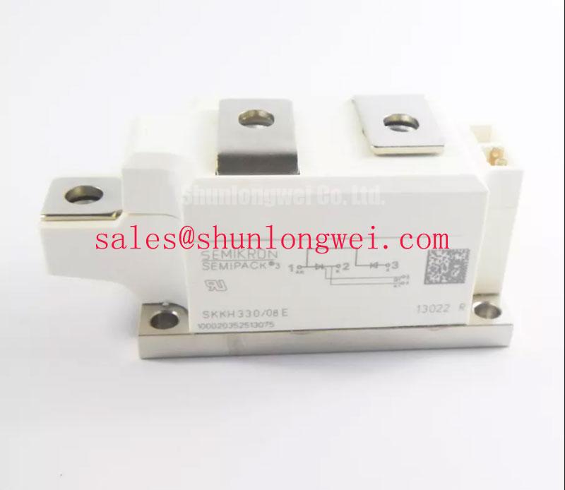
Where a repair review requires a related higher-current thyristor-diode module, the SKKH330/08E can be examined as a separate device option. Its electrical ratings, terminal arrangement, protection requirements, mechanical dimensions, and circuit role must be checked independently; it is not an automatic replacement for the SKKH273/18E. In rectifier systems using a complementary controlled stage, the SKKT500/08E may also be relevant to a broader topology review, subject to the original schematic and operating limits.
Field Diagnostics & Commissioning: Surge Energy Dissipation and Clamping Volt in SKKH273/18E Topologies
After an AC-side disturbance, begin with non-energized inspection. Check fuse bodies and holders, MOV condition, RC snubber components, gate lead insulation, terminal hardware, and the module baseplate for mechanical evidence of overheating or tracking. With the module disconnected as required by the service procedure, compare terminal behavior against the published circuit diagram and against a known-good channel if the equipment provides one. A cold meter check can identify an obvious short or open path, but it cannot validate blocking performance at operating voltage or commutation behavior at load.
The 9000 A non-repetitive surge current rating and 405000 A²s rating provide official device limits for fault analysis under their stated 25°C, 10 ms condition. They do not establish the energy capability of an installed surge suppressor or the clearing performance of a fuse. As a design consideration, MOV and RC snubber selection should be based on the AC source, transformer behavior, expected surge waveform, insulation coordination, repetitive duty, and measured clamp voltage. The system engineer should validate peak device voltage during representative switching and surge tests.
For surge immunity discussions, use the applicable IEC 61000-4-5 test framework at equipment level where it applies. A power semiconductor module is not independently an EMC-compliant finished system. Cabinet wiring, shielding, earthing arrangement, transformer coupling, external cabling, and the selected protective network all affect the observed result.
During commissioning, bring the repaired stage up under the original controlled procedure and monitor input current, DC output voltage, heatsink temperature, and phase symmetry. If clamping activity, repetitive fuse heating, or asymmetric waveforms are observed, stop escalation to higher load until the protection network and firing sequence have been reviewed. The practical test sequence and acceptance limits remain determined by the equipment manufacturer and site safety procedure.
Benchtop Waveform Tuning: Mitigating Stress via Type 2 Coordination: Sub-Cycle Dead Short on SKKH273/18E
Type 2 coordination is a system-level objective involving the semiconductor device, semiconductor fuse, contactor behavior, buswork, transformer source impedance, enclosure, and fault-clearing path. It cannot be guaranteed from the SKKH273/18E ratings alone. A dead short can develop on a sub-cycle timescale, and the relevant question is whether the selected protective assembly limits current and clears the fault before device and adjacent equipment limits are exceeded.
Use the official 405000 A²s device I²t value as a comparison reference when reviewing fuse time-current and let-through energy data under the stated test condition. The fuse manufacturer’s published pre-arcing and total-clearing information must be evaluated at the prospective short-circuit current of the installed system. Because junction temperature before the event, fault inception angle, conductor impedance, and source characteristics alter the real event, the comparison is an engineering calculation and validation exercise, not a fixed universal fuse prescription.
A useful bench investigation records current and voltage together during controlled fault testing performed within an approved test environment. Inspect whether the protective device clears as intended, whether the module experiences abnormal voltage excursion, and whether busbar joints or clamps show movement after the event. Do not use the 9000 A surge figure as a repetitive operational current allowance. It is specified as a non-repetitive 10 ms capability at 25°C, so prior thermal loading matters when evaluating fault tolerance.
For repair engineers comparing voltage headroom, thermal paths, protection coordination, package fit, and measured waveform margins, this Power Semiconductor Selection Guide provides a structured reference for documenting those checks. Return the SKKH273/18E stage to service only after terminal connections, thermal mounting, firing sequence, protection coordination, and load waveforms have been verified against the original equipment requirements.