Content last revised on September 15, 2026
SKKH273/16E Inspection and Specification Overview
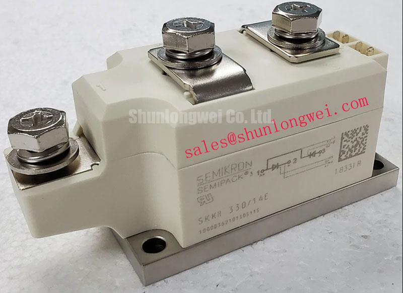
With the cabinet isolated and discharged, first verify the installed device marking, inspect the power terminals for heat discoloration or looseness, and compare the rectifier or controller voltage boundary with the 1600 V VRRM / VDRM rating of the Semikron SKKH273/16E. This is a high current thyristor module rated at 273 A mean on state current at TC = 85°C, intended for controlled power conversion stages where line voltage, surge energy, heatsink contact, trigger timing, and protective coordination must be checked as one system.
The official specifications identify a 9100 A 10 ms surge on state current, a 0.9 V threshold voltage, 0.11 K/W junction to case thermal resistance, and 3600 V~ isolation voltage. Each value is an Official Datasheet Specification and should be used to confirm the original equipment boundary, not as a standalone promise of suitability after a circuit redesign. For product family context, Semikron describes its SEMIPACK® thyristor and diode module platform as a power module range for industrial conversion equipment.
SKKH273/16E Operational Boundaries: Reverse Recovery and Temperature Limits
Before replacing a failed power module in a controlled rectifier, begin with the device's role in the commutation path. The SKKH273/16E is specified for repetitive peak reverse or off state voltage of 1600 V. In field service, that rating should be compared against the actual supply arrangement, transformer secondary voltage, firing sequence, cable routing, snubber network, and transient behavior measured at the module terminals. A nameplate voltage check alone cannot reveal switching overshoot caused by layout inductance or a degraded suppression network.
The supplied official parameter set does not state reverse recovery peak current, reverse recovery time, reverse recovery charge, fuse I²t coordination values, terminal screw torque, or a package terminal map. These values should therefore be verified from the original equipment documentation and the applicable manufacturer datasheet revision before they are used in a repair decision. It is not technically sound to infer diode recovery behavior from the 1600 V and 273 A ratings alone.
Where the converter includes a freewheeling diode, commutating diode, or a separate rectifier stage, reverse recovery interaction can influence the turn on and turn off stress seen by the thyristor path. Design Consideration: review oscilloscope captures from a known good phase where possible, using suitably rated isolated measurement equipment. Compare the timing of voltage reversal, current transfer, gate trigger pulse, and any ringing at the module terminals. A sharp recovery event can arise from several interacting conditions, including diode characteristics, cable inductance, transformer leakage inductance, timing imbalance, or a changed snubber component.
In induction melting or metal hardening power equipment, firing angle control can vary greatly as output power is regulated. This changes current transfer conditions from one operating point to another. Engineers should verify waveform behavior at the low and high ends of the commanded heating range rather than validating only one stable production setting. The module should remain within its official voltage and current ratings under the actual waveform and enclosure temperature conditions established by the machine.
Metal oxide varistors and RC suppression parts are often present around industrial converter sections to limit transient voltage exposure. Their selection is system dependent. Design Consideration: inspect these components for cracking, thermal discoloration, leakage evidence, or altered capacitance where test methods permit. Any replacement value must follow the original circuit documentation because an unsuitable MOV clamping level or snubber network can alter commutation behavior and increase repetitive stress.
If a maintenance evaluation identifies a need for a related higher voltage family reference, the SKKH273/18E can be examined as a separate specification reference. It should not be treated as an automatic substitute. Engineers must verify terminal arrangement, triggering requirements, thermal interface, insulation arrangement, mechanical fit, and the complete electrical ratings of the original assembly.
SKKH273/16E Circuit Protection & Reliability: Post-Surge Reverse-Voltage Assessment
The official ITSM rating of 9100 A for a 10 ms surge describes short duration surge capability under stated datasheet conditions. It does not establish an unlimited fault tolerance level for a furnace supply, motor controller, or controlled DC power stage. After a line fault, transformer inrush event, load short circuit, or commutation fault, the repair process should establish whether the protective device cleared the fault as intended and whether the converter was exposed to repeat surge events before shutdown.
Start with objective checks. Inspect semiconductor fuses, fuse holders, busbar joints, contactors, transformer connections, current sensors, and the load circuit. A fuse that has opened may be evidence of a preceding fault but does not independently identify the failing component. Similarly, a low resistance reading across a module path can indicate an internal fault, while an apparently normal static meter test cannot prove correct dynamic blocking or triggering performance.
For an installed unit, isolate associated gate drive circuitry before resistance testing whenever the service procedure allows it. Trigger transformers, optocouplers, digital isolators, pulse shaping networks, and controller outputs can create misleading readings if they remain electrically connected. Design Consideration: verify the integrity of the isolation barrier and the gate pulse path against the known good channel or original circuit documentation. Common mode transient performance is determined by the complete drive board, isolation component, grounding structure, and power layout rather than by the SKKH273/16E alone.
After a surge event, do not reapply reverse voltage merely because the module has cooled to ambient temperature. Inspect the heatsink interface, check for deformation around mounting locations, confirm that the external protection circuit is intact, and review whether the original fault source has been removed. The official 1600 V repetitive reverse or off state rating remains the electrical boundary, but the peak stress at the device is determined by the real circuit waveform. Engineers should verify peak margins against the DC link or line commutation voltage during controlled switching tests.
⚠️ Field Alert: Tighten module and busbar hardware evenly to the original equipment procedure, because uneven contact pressure or a loose power joint can create localized heating before protective devices respond.
For converter stages that use a complementary controlled power path, the SKKT273/12E is a related power module reference that may appear in broader equipment evaluations. Its presence in a topology does not establish electrical interchangeability with the SKKH273/16E. The original schematic, firing configuration, isolation arrangement, and thermal installation must govern service decisions.
SKKH273/16E Thermal Management: Ensuring Uniform Heatsink Contact Pressure
Thermal inspection begins at the case to heatsink interface. The SKKH273/16E has an official junction to case thermal resistance of 0.11 K/W. This value describes the thermal path from semiconductor junction to the module case under datasheet conditions. It does not include the thermal compound layer, mounting pressure, heatsink flatness, airflow, liquid cooling circuit, cabinet temperature, or contamination on the cooling surface.
Remove the module only after the system is fully isolated and stored energy has been discharged through the approved service procedure. Examine the mating heatsink surface for corrosion, embedded debris, raised burrs, old hardened compound, or uneven witness marks. These conditions can prevent uniform contact even if the module hardware appears tight. Clean the surfaces using methods compatible with the equipment maintenance instructions, then use an even, thin thermal interface layer as specified by the original equipment builder.
Design Consideration: apply mounting hardware progressively and in a balanced sequence so the module seats evenly against the heatsink. The applicable tightening torque must be taken from the module mechanical datasheet or machine service documentation because no mounting torque value is included in the supplied official specification set. Excess force can distort the assembly or damage threads, while insufficient force can increase contact thermal resistance.
During recommissioning, compare temperatures between parallel current paths, similar phases, or a known good module location using appropriate measurement methods. Uneven temperature distribution may be associated with heatsink contact, airflow obstruction, current imbalance, firing asymmetry, busbar resistance, load behavior, or a control issue. It should be investigated rather than attributed to a single cause from one thermal image.
When parallel thyristor paths are used in the original converter, Design Consideration: static and dynamic current sharing depends on matched device characteristics, symmetrical busbar geometry, equal cooling conditions, trigger timing, and circuit impedance. The positive temperature behavior of certain loss mechanisms cannot by itself guarantee safe sharing through a full firing and commutation cycle. System engineers should validate current distribution under controlled load tests.
The official 3600 V~ isolation voltage supports insulation separation between the specified module circuits and baseplate under its datasheet conditions. It is not a substitute for the equipment level creepage distance, clearance distance, enclosure pollution control, grounding, cable insulation, or high voltage test procedure. Where terminals have been serviced, inspect barriers, insulating covers, busbar spacing, and routing before energization. The complete assembly determines high voltage reliability.
Assembly Integrity & Layout Architecture: Implementing Harmonic Current Injection and Line Filter for SKKH273/16E
A thyristor controlled AC to DC section changes its average output and input current waveform as the firing angle moves from near zero toward delayed conduction. In a medium frequency induction melting or hardening furnace supply, this can alter transformer utilization, reactive power demand, harmonic current content, and stress on line side filtering. The SKKH273/16E should be evaluated as one part of that controlled conversion chain, with the firing angle and current waveform determined by the furnace power controller and load condition.
At earlier firing angles, the rectifier may transfer energy over a wider part of the AC cycle. At more delayed firing angles, the converter can draw current in a narrower interval and increase reactive demand. This is a circuit operating principle, not an official performance claim for this specific module. Engineers servicing an existing unit should compare the controller command, synchronization reference, gate pulse arrival, phase sequence, and measured line current waveform before changing filter components or adjusting firing parameters.
Line reactors, harmonic filters, transformer impedance, and capacitor banks are system components selected around the converter. Engineering Recommendation: retain the original topology unless qualified measurements and the equipment documentation support a change. A line filter can affect supply current distortion, but it may also interact with source impedance and converter commutation. The proper result depends on the supply network, transformer, load profile, control loop, and applicable equipment standards.
Gate pulse quality is particularly important when the system operates through a broad firing range. Inspect pulse transformer connections, optically isolated driver outputs where present, gate return routing, connector seating, and synchronization signals. Keep high current power loops compact where practical to suppress inductive overshoot during commutation, then verify the result by measuring the actual terminal waveform with an appropriate test setup. For service teams reviewing trigger synchronization, isolation practice, and switching test discipline, Precision Gate Drive Design provides relevant technical context.
Do not treat the SKKH273/16E as independently compliant with equipment level EMC requirements. Conducted and radiated behavior depends on the complete furnace cabinet, switching sequence, cable routing, grounding, enclosure, filters, and connected load. Following repair, confirm that busbar covers, terminal shields, grounding bonds, phase identification, and control connectors are restored before controlled energization. Verify operation at the equipment's approved commissioning points, with protection functions active and measured values compared against the original service limits.