






Content last revised on September 17, 2026
SKKT 253/16E Replacement Review and Rated Operating Limits
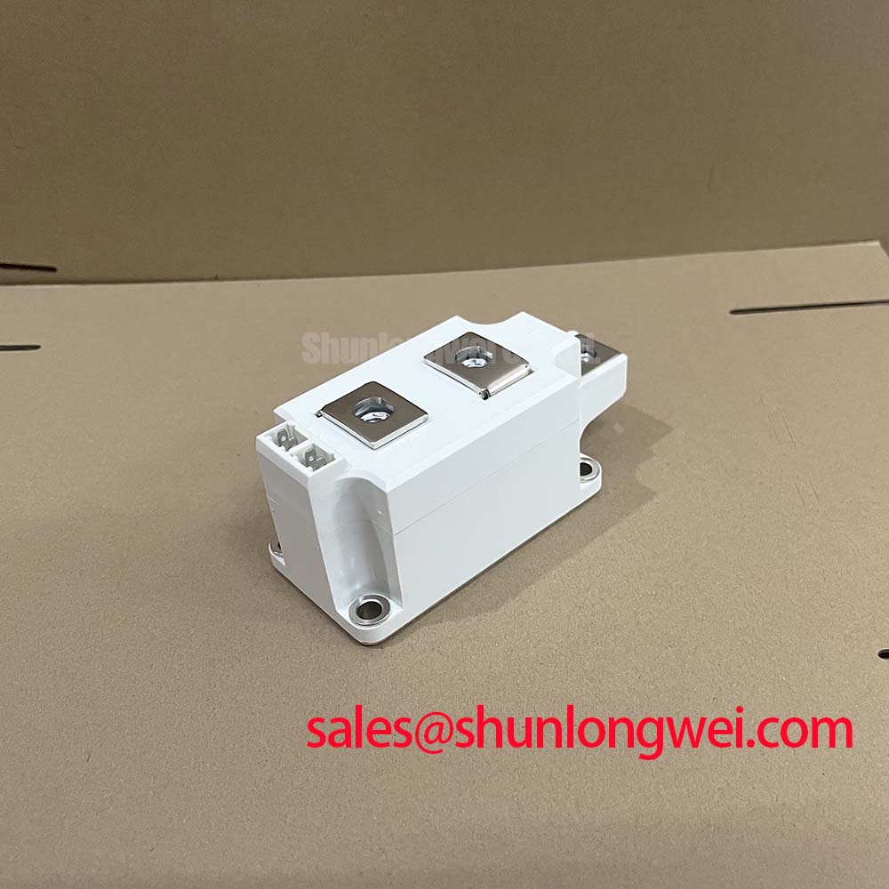
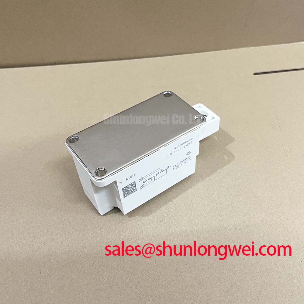
With the cabinet isolated and discharged, first compare the power terminal layout, gate connections, heatsink contact face, and original nameplate rating against the replacement position before fitting the SKKT 253/16E. This Semikron dual thyristor module is officially rated at VDRM/VRRM 1600 V and ITAV 253 A at Tc = 85 °C. It should be assessed as a controlled rectifier or AC power control device, not as an IGBT or a diode recovery module.
| Official Specification | Value and Condition | Integration Relevance |
|---|---|---|
| Repetitive peak off state voltage | 1600 V VDRM/VRRM | Defines the repetitive blocking voltage limit. |
| Average on state current | 253 A at Tc = 85 °C | Defines continuous current capability at the stated case temperature. |
| Surge on state current | 9000 A at 10 ms, Tvj = 25 °C | Applies to a non repetitive sinusoidal surge condition. |
| Junction to case thermal resistance | 0.10 K/W per thyristor | Supports heatsink and thermal interface assessment. |
| Maximum junction temperature | 130 °C | Sets the semiconductor thermal operating boundary. |
SKKT 253/16E Circuit Protection and Reliability: Interpreting Commutation Behaviour
Before investigating a suspected commutation fault, distinguish the device topology from the fault language used on the service report. The SKKT 253/16E is a thyristor module, so diode reverse recovery peak current and soft recovery time are not official characteristics supplied in the stated module data. Those values must not be assumed from another Semikron device family or inferred from a converter waveform.
For a controlled rectifier, unstable current transfer can instead involve source inductance, commutating capacitors, transformer leakage, gate pulse timing, load current, or an external freewheeling diode path. A scope check should compare gate pulse presence with anode to cathode voltage and load current on both controlled paths. If the waveform differs from a known healthy phase, inspect the associated gate drive wiring, connector retention, snubber parts, and busbar joints before attributing the event to the module.
The official 1600 V VDRM/VRRM rating is the voltage identity to retain during replacement review. It is not a system instruction to omit surge suppression. Design Consideration: protection coordination should limit repetitive and exceptional voltage stress at the thyristor terminals while allowing the equipment designer to verify actual peaks under the original line, transformer, and load conditions.
Fuse selection requires the fuse manufacturer’s time current and clearing energy documentation together with the converter fault study. No fuse I²t coordination value is stated in the provided product data, so a particular fuse cannot be declared suitable from the module current rating alone. Confirm that branch protection, cable capacity, contactor interruption duty, and semiconductor surge withstand are evaluated as one fault clearing path.
Field Alert: Tighten power and gate connections only to the equipment and module documentation requirements, because an uneven mounting interface or loose terminal can create heat and unstable triggering that a static meter test will not reveal.
For product family context, Semikron identifies its SEMIPACK thyristor and diode modules as power module solutions for controlled power conversion. The replacement decision still depends on the exact circuit arrangement, terminal mapping, gate polarity, heatsink interface, and original equipment documentation.
Transient Dynamics and Electrical Design: Non Repetitive Surge On State Current on SKKT 253/16E
The 9000 A ITSM figure is an Official Specification for a 10 ms sinusoidal half cycle with the junction initially at 25 °C. It is a non repetitive surge capability, not a continuous overload rating and not a substitute for coordinated fault protection. In field service, this distinction matters when a furnace supply has experienced transformer energization, a shorted load section, or an upstream switching event.
After a high current incident, do not re energize solely because the module appears intact. With the assembly isolated, compare the two thyristor paths for abnormal low resistance or obvious asymmetry, check gate circuit continuity against the original schematic, and examine the heatsink contact area, terminals, fuses, and bus connections. A basic multimeter check is a screening step only. Controlled thyristor behaviour, leakage under blocking voltage, and triggering consistency require appropriately rated test equipment and a safe procedure.
The junction temperature boundary is officially 130 °C Tvj max. Engineering Recommendation: treat recovery time after a surge as system determined. It depends on the starting temperature, pulse shape, energy path, heatsink condition, airflow, thermal interface condition, and the equipment’s own protection sequence. The system engineer should verify that reverse voltage is not reapplied until measured electrical and thermal conditions are within the converter design limits.
In medium frequency induction melting or hardening furnace power equipment, the module can be evaluated in the controlled input or rectification section when its electrical topology matches the existing design. It should not be presented as a direct replacement merely because another module has a similar current number. For comparison during a documented redesign review, the SKKT 250/14E provides a separate reference point, but its voltage class, connections, thermal behaviour, and circuit suitability must be checked independently.
SKKT 253/16E Operational Boundaries: Evaluating AC Input Transient Overvoltage Clamping Limits
Start transient investigation at the actual module terminals rather than at the incoming cabinet supply. Long conductors, transformer leakage, busbar geometry, switching contactors, and the commutation network can all change the voltage seen by the thyristor. The 1600 V VDRM/VRRM value defines the module’s repetitive off state blocking limit, while the clamp network must be validated against measured equipment transients.
Design Consideration: an MOV at the input and an RC network located according to the original converter layout can address different transient paths. An MOV is typically evaluated for incoming line surge energy and clamping behaviour. An RC snubber is evaluated for local thyristor voltage rise and ringing. Neither component should be selected from the SKKT 253/16E voltage rating alone. The equipment designer should test peak terminal voltage, repetitive energy, and temperature rise under the complete operating range.
Where surge immunity is part of a customer or machine requirement, use the applicable system standard and test plan rather than assigning compliance to this module. IEC 61000 4 5 addresses surge testing at equipment level; a discrete power module does not independently establish complete equipment surge or EMC compliance.
Terminal insulation distances, enclosure contamination, and wiring routing also deserve inspection after an overvoltage event. A cracked snubber capacitor, heat discoloured resistor, displaced bus support, or damaged suppression component can leave a replacement module exposed to the same transient that damaged the previous installation. The module data provides no separate insulation reliability claim beyond the listed electrical ratings, so the system integrator should verify insulation conditions from the original equipment documentation.
Thermal interface materials and enclosure plastics should also be treated by their actual specified properties rather than assumptions. For general material background, polyphenylene sulfide is widely discussed as a high temperature engineering plastic, but this reference does not identify the internal construction or material composition of the SKKT 253/16E.
SKKT 253/16E Thermal Electrical Optimization: RC Snubber Tuning Without Practical Guesswork
The starting point for thermal review is the official 0.10 K/W junction to case thermal resistance per thyristor. This value describes the internal path from each thyristor junction to the case under the stated datasheet basis. It does not include thermal compound, mounting flatness, heatsink resistance, airflow, ambient temperature, or the heat generated elsewhere in the converter. Those external elements determine whether the case temperature remains compatible with the 253 A at Tc = 85 °C current condition.
Design Consideration: apply the thermal interface evenly, maintain a clean flat contact surface, and verify that the heatsink assembly follows the mounting hardware requirements. A measured case temperature is useful only when interpreted with current waveform, firing angle, duty cycle, cooling state, and the actual position of the sensor. Do not use a single case measurement to claim junction temperature compliance without the system thermal model or validated test method.
RC snubber adjustment should begin with the original schematic values and measured waveforms, not a generic capacitor and resistor pair. Designers should minimize the loop formed by the thyristor, snubber, and associated conductors to suppress local ringing. They should then verify terminal voltage, gate timing, resistor heating, capacitor stress, and repeatability during the operating conditions that produce the highest commutation disturbance.
A series saturable reactor, where present in the established circuit, also changes current rise behaviour and commutation interaction. Its suitability is determined by the existing magnetic design, current waveform, and protection philosophy. It should not be added or resized from the module nameplate alone. For broader thermal integration principles, consult The Advanced Thermal Management Revolution while keeping the final heatsink and snubber validation specific to the installed power assembly.
