Content last revised on October 29, 2026
FZ1200R17HP4_B2 Maintenance Checks and Product Ratings
- Isolate the equipment, verify DC-link discharge, and compare cold terminal measurements with the circuit diagram before disconnecting the module.
- Record the complete FZ1200R17HP4_B2 designation and check the replacement against the installed assembly drawing.
- Inspect the heatsink contact surface, mounting hardware, and thermal interface for contamination, uneven seating, or displaced material.
- Trace the gate-driver return connection and inspect its separation from the main load-current path.
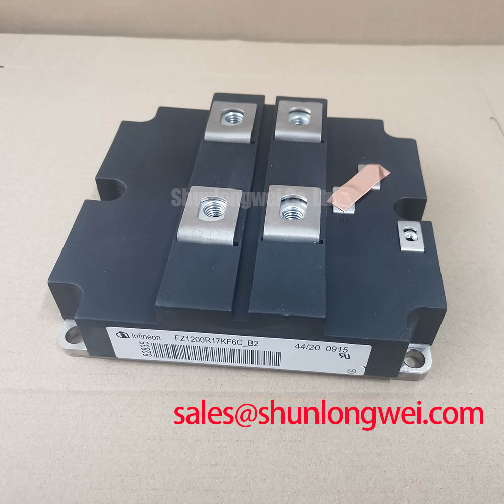
The Infineon FZ1200R17HP4_B2 is an IGBT module with a 1700 V voltage rating and 1200 A current rating. Maintenance decisions should connect these electrical ratings to the actual driver, cooling assembly, and protection circuit rather than treating a matching current designation as sufficient replacement evidence.
| Product attribute | Value | Specification status |
|---|---|---|
| Manufacturer | Infineon | Product identity |
| Model | FZ1200R17HP4_B2 | Complete ordering designation |
| Rated voltage | 1700 V | Official Specification |
| Rated current | 1200 A | Official Specification; operating conditions apply |
| Package | Module | Official Specification |
| Terminal assignments, dimensions, mounting limits, and dynamic characteristics | Consult Datasheet | Required for assembly approval |
Assembly Integrity & Layout Architecture: Assessing High-Altitude Cosmic-Ray-Induced SEB Risk for FZ1200R17HP4_B2
Separate steady blocking voltage from switching overshoot when reviewing the DC-link operating envelope. Design Consideration: cosmic-ray-induced single-event burnout assessment requires device-specific manufacturer evidence and the installation’s environmental profile; the 1700 V rating alone does not establish a cosmic-ray failure rate or an altitude derating curve.
For an elevated installation, the useful maintenance record includes site elevation, normal and maximum DC-link voltage, measured switching peaks, and relevant operating temperatures. A reliability review should use manufacturer-supported susceptibility information to evaluate those conditions. Applying an arbitrary voltage reduction or calculating FIT from elevation alone would not establish an acceptable operating point.
Keep the assembly review practical: inspect busbar supports, contamination paths, conductor spacing, and the condition of insulating barriers. Clearance and creepage requirements depend on the equipment’s insulation coordination, environmental conditions, and applicable standards, rather than a universal module-specific distance. The Infineon IGBT Modules & Discretes Official Portfolio provides manufacturer context for the relevant device families.
For compatibility assessment, a utility-scale centralized battery energy storage PCS is one possible application, subject to its topology, cooling capacity, and protection requirements. During procurement comparison, treat FZ1200R12KL4C as a separate reference model, not an approved equivalent: compare blocking capability, terminal geometry, switching behavior, and mechanical interfaces before considering substitution.
Assembly Integrity & Layout Architecture: Implementing Auxiliary Emitter Pinout Cold-Check for FZ1200R17HP4_B2
Trace the driver return on the assembly drawing before using a continuity reading to identify an emitter connection. Electrically connected terminals can perform different circuit functions, and a cold resistance measurement does not reveal the inductance shared with the load-current path.
Design Consideration: where the manufacturer terminal drawing identifies an auxiliary emitter connection, the driver return should follow that designated connection rather than an improvised route through the power busbar. This reduces shared-inductance coupling into the gate loop. It does not justify assigning an undocumented Kelvin terminal to this model or assuming that continuity establishes the correct pinout.
Inspect connector engagement, return-path routing, and the physical separation between gate wiring and switching conductors. During controlled testing, measure gate-to-emitter voltage at the relevant device connections with an appropriately rated differential measurement arrangement. Compare commanded transitions with local gate behavior; a driver-board waveform alone can miss disturbances introduced between the board and module.
For parallel assemblies, assess symmetrical power paths, comparable cooling contact, and matched driver timing. A positive temperature coefficient of on-state voltage can assist static sharing only within the operating region established by the device characteristics; it does not guarantee dynamic current balance. The Infineon IGBT Modules Overview is a manufacturer reference for module-family evaluation, while the exact characteristic curves govern the sharing assessment.
Thermal Interface Maintenance: Preventing Thermal Paste Degradation on FZ1200R17HP4_B2
Inspect the thermal interface whenever the module is removed, and preserve photographs of its contact pattern before cleaning the mating surfaces. Uneven transfer, displaced compound, or localized contamination can help explain a thermal change, but none independently proves the cause of overheating.
Engineering Recommendation: use the module’s mounting instructions and the selected interface material’s application procedure to establish coverage, deposited quantity, and assembly sequence. Do not compensate for a damaged or distorted mounting surface by adding an uncontrolled layer of paste. Flatness checks and any baseplate-curvature allowance belong to the approved mechanical assembly process.
Apply the specified screw-tightening sequence with a calibrated tool, keeping baseplate mounting requirements separate from electrical-terminal requirements. Repeated tightening is not a substitute for inspection: an altered thermal trend can also reflect restricted airflow, changed coolant conditions, or increased electrical losses.
Maintenance Note: Trend terminal and heatsink temperatures under comparable load conditions, and inspect cooling passages for dust accumulation before changing driver settings.
Set inspection intervals from the equipment service plan and observed contamination or thermal trends rather than an invented paste-replacement calendar. After cold storage or temperature transitions, check for condensation before energization. When investigating an adjacent switching or auxiliary stage containing FZ1800R17KF4, evaluate its thermal path separately; its presence does not establish a rectifier function or compatibility with this module.
Preventing Spurious Faults: Suppressing C_res-Induced Gate Voltage Spikes in FZ1200R17HP4_B2
Capture the off-state gate voltage while the complementary switch commutates to determine whether collector-voltage transitions are coupling into the gate circuit. Design Consideration: reverse-transfer capacitance can inject gate current during rapid voltage changes, while shared return inductance and probe placement can alter the observed waveform.
A low-impedance turn-off path and an active Miller clamp are possible driver-level countermeasures. Their suitability depends on clamp timing, available sink capability, connection inductance, and the module’s gate limits. Negative off-state bias is another system-dependent option, not a fixed voltage prescription for FZ1200R17HP4_B2. Validate the resulting gate excursions at the device connections across the intended operating envelope.
Review dead time against actual switching delays, driver propagation variation, and temperature-dependent behavior. Excessively short separation can permit cross-conduction; excessive separation changes diode conduction and converter behavior. Establish timing through the equipment’s validation procedure rather than assuming a universal microsecond buffer.
Desaturation protection should coordinate detection blanking, fault recognition, and controlled turn-off with the device’s documented short-circuit limits. Soft turn-off can reduce interruption stress, but must remain compatible with the permitted fault duration. The 10µs Lifeline explains the protection principle; its title must not be interpreted as this module’s short-circuit rating. Where the equipment includes a regenerative braking chopper, verify chopper operation and resistor energy absorption separately, since DC-link overvoltage and unintended gate turn-on require different corrective actions.