
Content last revised on May 4, 2026
FZ1800R17KF4: Unleashing Megawatt Scalability Through Advanced Thermal Management
Highlight Overview
Defining Robustness in Single-Switch Power Architecture
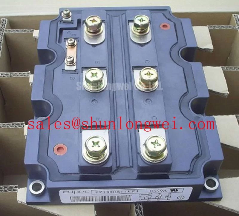
The FZ1800R17KF4 establishes a definitive baseline for thermal resilience and scalability in multi-megawatt power infrastructure. Core specifications include: 1700V | 1800A | Single Switch Configuration. This architecture actively eliminates structural bottlenecks in phase-leg construction and drastically reduces thermal fatigue during cyclical loading. Why choose a single-switch format? It maximizes layout flexibility and minimizes stray inductance in megawatt-scale phase legs. For central solar inverters prioritizing thermal margin and phase-leg scalability, this 1700V/1800A module is the optimal choice.
Key Parameter Overview
Decoding Specifications for Heavy-Duty Reliability
To support rigorous system evaluation, the critical specifications are functionally categorized below, reflecting the module's capacity for extreme power handling.
| Functional Group | Parameter | Rated Value / Characteristic |
|---|---|---|
| Maximum Rated Values | Collector-Emitter Voltage (VCES) | 1700V |
| Continuous DC Collector Current (IC nom) | 1800A | |
| Repetitive Peak Collector Current (ICRM) | 3600A (tp = 1 ms) | |
| Thermal & Mechanical | Configuration | Single Switch (IHM Package) |
| Maximum Junction Temperature (Tvj max) | 150°C |
Download the FZ1800R17KF4 datasheet for detailed specifications and performance curves.
Application Scenarios & Value
Achieving System-Level Benefits in High-Surge Infrastructure
Engineers architecting high-capacity UPS systems consistently face the challenge of managing immense inrush currents during grid transfer events or downstream short circuits. Utilizing multiple smaller modules in parallel often introduces severe current-sharing imbalances and parasitic inductance issues. The FZ1800R17KF4 directly solves this by providing a massive 1800A continuous and 3600A peak current capability within a single cohesive housing. By deploying this single-switch module, designers can construct highly symmetric, low-inductance phase legs that effortlessly handle transient overloads without triggering nuisance trips or stressing the semiconductor beyond its safe operating area.
Furthermore, in environments strictly governed by IEC 61800-3 EMC requirements for variable speed drives, simplifying the DC busbar geometry—made possible by using fewer, higher-current modules—significantly curtails radiated emissions. While this unit delivers exceptional performance for the majority of heavy industrial drives, systems demanding even higher current headroom for extreme continuous loading might consider the related FZ2400R17HP4_B2, which expands the nominal rating to 2400A.
Technical Deep Dive
The Mechanics of Thermal Cycling and Paralleling Scalability
At the megawatt level, electrical performance is entirely dictated by thermomechanical execution. The FZ1800R17KF4 utilizes an industrial-grade IHM (IGBT High-Power Module) housing, which is specifically engineered to combat the differing coefficients of thermal expansion (CTE) between the silicon die, the isolation substrate, and the baseplate. You can think of the module's heavy copper baseplate as a massive thermal shock absorber; it aggressively buffers the active silicon from rapid, localized temperature spikes during severe operational transients, thereby extending the power cycling lifecycle.
When system demands exceed 1800A, engineers must parallel multiple phase legs. The single-switch topology of this module is paramount here. Unlike half-bridge configurations where internal layout asymmetry can skew current distribution, a single-switch module allows engineers to design perfectly mirrored external busbar architectures. This external symmetry is like building a highway with dedicated heavy-load lanes instead of forcing traffic through a single, split-lane bottleneck—it ensures identical stray inductance paths, guaranteeing that static and dynamic current sharing remains precisely balanced across all paralleled components.
Frequently Asked Questions
Engineering Insights for System Integration
- How does the single-switch configuration of the FZ1800R17KF4 benefit multi-megawatt phase-leg design?
It grants power engineers total control over the external busbar geometry. By decoupling the top and bottom switches of a half-bridge into separate packages, designers can optimize the layout for absolute lowest stray inductance and symmetrical current distribution, which is critical when paralleling modules for inverter capacities exceeding 1.5MW.
- What is the engineering significance of its high ICRM (3600A) rating in heavy-duty applications?
The 3600A repetitive peak current rating ensures massive dynamic headroom. In applications like heavy traction or industrial crushers, this allows the system to ride through severe mechanical locked-rotor conditions or aggressive acceleration profiles without exceeding the safe operating limits of the silicon, effectively preventing catastrophic thermal runaway.
To secure optimal power architecture for your next high-current application, consult our engineering resources or request a detailed evaluation of this module's integration parameters.