

Content last revised on November 6, 2026
Preventing Spurious Faults: Static and Dynamic Current Distribution Guidelines for FF800R17KE3
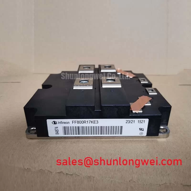
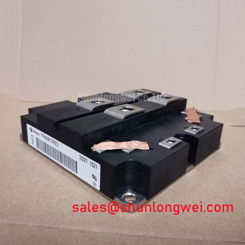
When a parallel IGBT branch trips or runs hotter than its neighbor, compare the current paths and gate-drive wiring before changing protection thresholds. The FF800R17KE3 is an Infineon IGBT module with a dual half-bridge topology and IGBT3 High Speed series designation. Its 1700.0 V collector-emitter rating and 800.0 A continuous collector-current rating are official product parameters, not a complete system operating envelope.
For static current sharing, a positive temperature coefficient in on-state voltage can support balancing under appropriate operating conditions: as a device junction warms, its on-state voltage may rise, tending to redistribute current. Treat this as a design consideration, not a guarantee of equal current. Compare module temperatures, measured branch currents, and operating conditions at a stable load. Differences can also arise from unequal busbar resistance, contact condition, cooling, or device characteristics.
Dynamic sharing depends strongly on the complete commutation and gate-drive paths. Keep corresponding gate and emitter routes as symmetrical as practical, and avoid routing one module’s drive return through another module’s high-current path. During troubleshooting, capture gate-emitter and collector-emitter waveforms with suitable differential probes and compare branches under the same switching conditions. Check whether ringing or switching delay differs before adjusting protection settings.
For a potential utility-scale 1500 V central solar photovoltaic inverter application, assess the module against the inverter’s DC-link arrangement, switching conditions, cooling system, and protection strategy. The system voltage label alone does not establish compatibility. When replacing a module, compare the original circuit topology, terminal arrangement, driver interface, and thermal interface rather than relying on current and voltage ratings alone.
Field Diagnostics & Commissioning: Balancing Switching Dissipation vs di/dt in FF800R17KE3 Topologies
When retrofitting an IGBT module into a legacy drive board, document the existing turn-on and turn-off gate-resistor paths before energizing the assembly. Gate resistance affects switching speed and dissipation, while the circuit’s parasitic inductance and load conditions influence ringing and voltage overshoot. There is no universal resistor value that can be specified from the module’s headline ratings alone.
As an engineering recommendation, tune turn-on and turn-off resistance separately only where the driver design supports separate paths. Change one circuit variable at a time, then compare switching waveforms, device temperature, and fault behavior across the intended load range. A change that reduces ringing may increase switching loss; one that reduces switching loss may increase di/dt or overshoot. The acceptable balance is system-dependent and must be established in the actual converter.
For parallel modules, symmetrical busbar geometry and matched gate-loop routing help avoid unequal transient current. Inspect the physical current path from the DC-link capacitor through the power terminals and back; a long or asymmetric branch can create different switching behavior even when the gate-drive commands match. If a drive board uses optical or digital isolation, review its common-mode transient immunity and layout in relation to the switching-node transitions. Confirm the isolator and driver behavior using the board’s design documentation and measured signals; do not assume isolation alone prevents false switching.
In regenerative systems, verify that the braking chopper and resistor network can absorb the energy demanded by the application. The IGBT module rating does not specify the braking resistor, chopper threshold, or permissible duty cycle. During commissioning, observe DC-link behavior during deceleration and confirm that the braking control, resistor thermal capacity, and overvoltage protection operate as intended.
For a broader discussion of motor-drive switching tradeoffs, see the Optimizing Motor Drive Systems Technical Reference.
Preventing Spurious Faults: Main Terminal Pinout Mechanical Alignment Guidelines for FF800R17KE3
Before tightening power connections, align the busbar and cable lugs so that the fasteners draw the conductors onto the terminals without forcing them sideways. Misalignment can load the terminal assembly mechanically, disturb contact pressure, and complicate reliable seating. Check the module’s terminal markings and the equipment wiring diagram against the circuit position; do not infer terminal identity from orientation alone.
Use the specified fastener type, washers, and tightening procedure from the applicable manufacturer documentation. Thread engagement must be sufficient for the joint while avoiding contact with internal structures. Do not treat a generic torque value as an FF800R17KE3 specification. If a busbar hole does not align freely, correct the busbar or support arrangement rather than using the screw to pull it into position.
After installation, inspect for tilted lugs, trapped debris, uneven contact surfaces, and signs that the conductor is bearing against neighboring parts. Maintain the electrical clearances required by the complete assembly’s voltage class and insulation system; the module’s 1700.0 V Vces rating does not define enclosure clearance by itself. Recheck the mechanical assembly after service where vibration or thermal cycling is relevant, following the equipment maintenance procedure.
Thermal-interface material should form a consistent, thin contact layer across the mounting surface without excess that can compromise seating. Clean both mating surfaces using a method compatible with the materials, and secure the module in the sequence prescribed for the assembly. Bench Tip: Use ESD controls and compare cold-state measurements with a known-good reference before interpreting diode-mode readings; parallel circuit paths can affect readings in-circuit.
FF800R17KE3 Thermal-Electrical Optimization: Auxiliary Kelvin Emitter vs Main Power Emitter Practical Tuning
Identify the module’s actual power and gate-drive connections from its terminal markings and manufacturer connection diagram before routing driver returns. Do not assume that a separately accessible auxiliary Kelvin emitter is present or that a particular terminal serves that function unless the module documentation confirms it. A driver return connected to the main load-current path can experience voltage disturbance from current transients, potentially changing the effective gate-emitter voltage.
Where the documented terminal arrangement provides a dedicated gate reference, route the driver return to that point using a compact loop separate from the main load-current path. Keep the gate path away from fast-switching nodes where practical, and inspect the board for shared return traces, long connector paths, or poor separation between control and power conductors. If the design has no dedicated Kelvin connection, preserve the intended reference arrangement shown in the circuit documentation rather than improvising a new connection.
During fault investigation, compare the driver output at the module terminals with the command signal at the driver input. Look for unexpected gate movement during switching transitions and assess whether the observation changes with load current or probe placement. Use appropriate isolated measurement techniques; a poorly referenced probe can produce misleading traces or create a hazardous measurement setup. Any gate-bias or damping change is an engineering adjustment that should be validated against the driver’s limits and switching behavior.
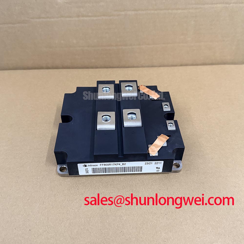
The FF800R17KE3 product category is IGBT Module, its package is Module, and its configuration is an IGBT Power Stage. For comparison within the same product family, review the FF800R12KE3 against the required voltage rating, current conditions, topology, and mechanical interface; do not treat it as an automatic substitute.