Content last revised on September 26, 2026
FF600R12KE4 Thermal Electrical Optimization: Kelvin Emitter Connection Practical Tuning
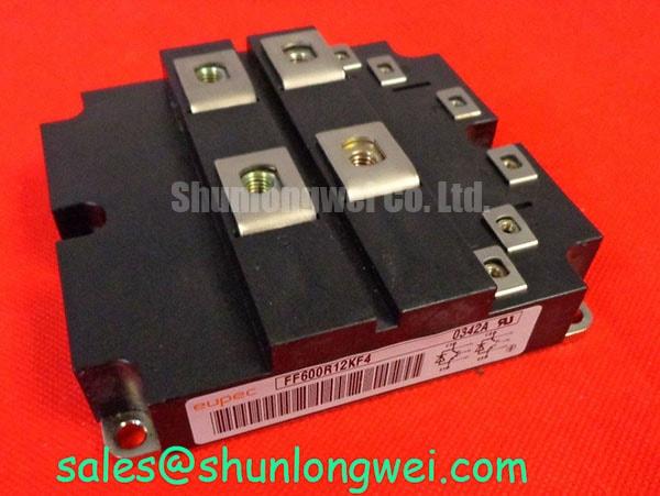
Begin service evaluation with the equipment isolated, then inspect the module body, terminal hardware, busbar interfaces, and gate wiring before applying a test voltage. The Infineon FF600R12KE4 is identified in the supplied product data as a 1200 V, 600 A IGBT module with a module package. These ratings are official product specifications for identification and initial electrical boundary checks; switching performance still depends on the complete converter design, cooling system, gate driver, and operating conditions.
For a high power wind turbine full scale converter, the practical concern is the separation of high current commutation paths from sensitive gate control returns. Where the module provides an auxiliary emitter or Kelvin emitter connection, the system designer should confirm the terminal function against the applicable Infineon documentation before wiring. The auxiliary emitter return should follow the intended gate driver reference rather than sharing an uncontrolled section of the main emitter busbar. This reduces mutual coupling and gives the driver a cleaner reference during rapid current transitions.
This is a Design Consideration, not an additional factory rating for the FF600R12KE4. Keep the power loop physically compact, avoid routing gate signals alongside high di/dt collector paths, and maintain consistent geometry between parallel switching positions. The final clearance and spacing must be set by the converter insulation system, working voltage, pollution environment, and applicable safety assessment. During commissioning, compare gate to emitter waveforms at the module terminals rather than relying only on measurements at the driver board.
If the waveform shows ringing, an unexpected plateau, or different turn off behavior between nominally symmetrical positions, inspect the gate loop, auxiliary emitter return, connector contacts, and busbar mounting surfaces. A known good switching position can provide a useful comparison, but a single waveform symptom should not be assigned to one cause without checking the complete signal path. The Precision Gate Drive Design reference provides a related engineering resource for evaluating gate loop behavior.
When reviewing the wider converter topology, the FZ800R12KS4_B2 may be assessed separately for an appropriate converter stage. It should not be treated as an automatic replacement for the FF600R12KE4. Electrical ratings, topology position, mechanical interfaces, gate requirements, and thermal conditions must be checked independently.
FF600R12KE4 Circuit Protection and Reliability: Calibrating Thermal Feedback
The stated 600 A current rating identifies the product class, but it does not by itself define allowable current in every wind converter operating point. The system engineer should verify switching frequency, duty cycle, junction temperature, case temperature, transient overload conditions, and the thermal impedance of the installed cooling assembly. A converter controller should use measured operating conditions and validated protection thresholds rather than treating the nameplate current as a universal continuous operating limit.
IGBT modules may exhibit temperature related changes in conduction voltage, and designers sometimes evaluate the resulting behavior when considering static current sharing. This mechanism should be confirmed from the applicable electrical characteristics for the exact device and operating point. It should not be used as a substitute for symmetrical gate wiring, matched power paths, current measurement, or validated protection logic. Dynamic sharing is strongly affected by stray inductance, gate resistance, driver propagation timing, and the physical arrangement of the busbars.
Before energizing a replacement module, verify every power and auxiliary terminal against the approved drawing. Do not infer pin functions from a visually similar module. Check continuity with the power stage isolated, inspect for unintended connections between control and power returns, and compare the installed busbar orientation with the original mechanical arrangement. The module package specification supplied here does not provide a detailed terminal map, so the system integrator should obtain that information from the relevant manufacturer documentation.
Protection coordination deserves the same attention as gate control. A fast semiconductor fuse, if used by the converter design, must be evaluated against the module short circuit withstand capability, fuse clearing behavior, available fault energy, and the complete cable and busbar inductance. The applicable I²t relationship is a system coordination calculation, not an FF600R12KE4 factory rating. Verify the selected fuse and protection sequence through documented design calculations and controlled testing.
For a wind turbine converter exposed to vibration and thermal cycling, inspect busbar supports, terminal surfaces, fasteners, and insulation barriers during scheduled service. The fastening method and torque must follow the module manufacturer’s mechanical instructions and the converter assembly specification. Maintenance Note: monitor abnormal contact temperature and clean the heat sink and airflow path during planned service, especially where salt, dust, or condensation can accumulate.
Assembly Integrity and Layout Architecture: Reinforced Insulation Barrier Integrity for FF600R12KE4
The 1200 V voltage rating is an official electrical specification for the device, but it is not a complete statement of the assembled converter’s insulation performance. Reinforced insulation, galvanic isolation, creepage, clearance, pollution level, altitude, material group, and enclosure conditions must be assessed at system level. Do not assume that a target such as greater than 5 kV isolation or a particular common mode transient immunity value applies to this module unless it is explicitly documented for the exact component and interface under review.
For a full scale wind turbine converter, inspect the physical separation between high voltage conductors, gate driver circuitry, sensing circuits, and grounded mechanical structures. Look for contamination tracks, damaged insulating sheets, loose barriers, compressed spacers, and busbar edges that could reduce the intended distance. Clearance is the shortest path through air, while creepage follows the insulation surface; both need to be checked against the design standard and the actual installation environment.
Gate driver isolation should be validated together with its local power supply, signal return, and mechanical mounting. A driver may show correct logic behavior on a bench while common mode current in the assembled converter disturbs the gate reference. Designers should minimize parasitic coupling, control the return path, and verify the gate to emitter voltage directly at the module during switching tests. The required transient immunity is determined by the driver, isolation barrier, layout, and switching conditions as a complete system.
If a converter exhibits intermittent gate activity, unexplained protection trips, or unequal phase behavior, first isolate the equipment and inspect the control harness, isolation components, shielding termination, and grounding arrangement. Compare the isolated driver supply and gate signals with the approved reference waveform. A suspected insulation problem should be evaluated with the test method and voltage limits specified by the responsible safety engineer; improvised high voltage testing can damage the module or create a personnel hazard.
Infineon’s IGBT Modules and Discretes Official Portfolio and IGBT Modules Overview are suitable starting points for confirming product family information and manufacturer documentation. The product page for the FF600R12KE4 should still be checked against the exact revision and application conditions before a maintenance release is approved.
FF600R12KE4 Circuit Protection and Reliability: Calibrating High dv/dt Cross Conduction Shoot Through
High dv/dt switching can couple energy into an adjacent gate loop through parasitic capacitance and shared impedance. The resulting disturbance may appear as a transient gate signal, abnormal current overlap, or a protection event, but the observation alone does not establish a single failure mechanism. Check the gate to emitter waveform at the module, the driver supply, the auxiliary emitter return, and the current probe installation before changing protection values.
An active Miller clamp can be considered where the selected driver supports that function and where its timing, current capability, isolation arrangement, and connection method suit the converter. A low impedance gate return is also a general Design Consideration, but its implementation must be determined by the driver manufacturer’s data and the actual switching loop. The supplied product information does not establish a required active clamp circuit or a mandatory negative gate bias for the FF600R12KE4.
Negative gate bias is sometimes evaluated for turn off robustness in high dv/dt applications. The appropriate value, polarity, transient behavior, and absolute gate emitter limits must come from the applicable device and driver documentation. The system designer should not apply a negative bias range simply because it is common in another IGBT platform. Verify the gate voltage during start up, normal switching, fault interruption, and driver undervoltage conditions.
Dead time and interlock logic should be checked at the actual driver outputs, not only in the controller firmware. Confirm that both complementary commands cannot overlap during reset, loss of isolated power, communication interruption, or protection recovery. Then verify the power stage with controlled tests while observing collector emitter voltage, phase current, gate emitter voltage, and temperature. Minimize the commutation loop and validate peak voltage against the 1200 V device boundary and the converter’s approved transient margin.
When a field unit is replaced, record the original wiring orientation, thermal interface condition, busbar support arrangement, and gate driver configuration before removal. The FZ3600R12HP4 can be reviewed as a separate Infineon module option during a neutral cross model assessment, but substitution requires confirmation of voltage, current, package, terminal assignment, gate characteristics, protection coordination, and thermal compatibility. After installation, perform insulation, gate signal, cooling, and low energy switching checks before returning the converter to service.