Content last revised on September 14, 2026
Transient Dynamics & Electrical Design: Semiconductor Protection Fuse Selection for SKKT 250/14E
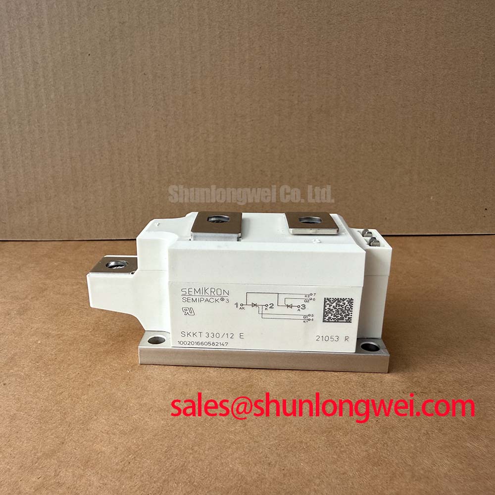
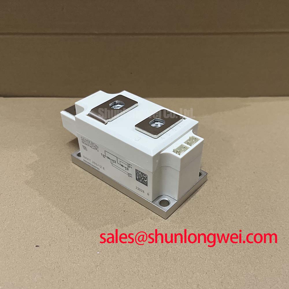
Before installation, verify the nameplate rating and check that the terminal layout, mounting face, and control connections match the removed SKKT 250/14E assembly. This Semikron thyristor and diode module is specified with 1400 V VRRM, 1400 V VDRM, and a 250 A mean on state current at TC = 85°C. Its published surge on state capability is 9100 A at 10 ms and 25°C. The module uses the SEMIPACK 3 housing and has a specified junction to case thermal resistance of 0.11 K/W, with maximum junction temperature rated at 125°C.
| Official Specification | Value |
|---|---|
| Repetitive peak reverse voltage, VRRM | 1400 V |
| Repetitive peak off state voltage, VDRM | 1400 V |
| Mean on state current, IT(AV), at TC = 85°C | 250 A |
| Surge on state current, ITSM, 10 ms at 25°C | 9100 A |
| Junction to case thermal resistance, Rth(j-c) | 0.11 K/W |
| Maximum junction temperature, Tvj | 125°C |
| Housing | SEMIPACK 3 |
In a controlled rectifier or AC power controller, fuse coordination should begin with the actual prospective fault current and the protective device clearing characteristic, rather than with the module’s nominal 250 A current rating alone. The 9100 A surge rating is an Official Specification under the stated 10 ms and 25°C condition. It is not a continuous fault withstand rating and should not be treated as permission for unrestricted short circuit energy.
For semiconductor fuse selection, the system engineer should compare the fuse pre arcing and total clearing I²t data with the complete fault path, including transformer impedance, busbar impedance, incoming supply behavior, and the protected device’s available surge documentation. A suitable coordination review considers whether the fuse can interrupt the fault before thermal and mechanical stress in the thyristor diode path becomes excessive. The fuse holder, conductor cross section, and terminal interfaces also require verification for the actual fault duty.
The SEMIPACK 3 module mounting arrangement should be assembled on a flat, clean heatsink surface with a uniform thermal interface material layer. Mounting torque is a Design Consideration and must follow the applicable mechanical documentation for the module hardware and heatsink. ⚠️ Field Alert: Tighten mounting hardware evenly in the specified sequence because uneven clamping can impair thermal contact and mechanically stress the module base.
Terminal joints should be checked for seating, conductor strain, and separation between power and gate wiring. Loose high current connections can add resistance and generate localized heating, while poor gate return routing can disturb firing behavior during high current commutation.
SKKT 250/14E Operational Boundaries: Evaluating AC Line Surge Immunity and Lightning Transients
The 1400 V VRRM and 1400 V VDRM ratings define the published repetitive reverse and off state voltage boundaries for SKKT 250/14E. They do not independently define the surge survival of an installed furnace power supply. In medium frequency induction melting and hardening equipment, upstream switching, transformer leakage energy, supply disturbances, and cable routing can create voltage events that require system level evaluation.
A Design Consideration is to coordinate the metal oxide varistor network, RC suppression network, incoming protective devices, and physical bus arrangement as one protection system. The MOV clamping behavior should be verified against the expected line transient environment and the actual DC or AC operating waveform. RC snubber values should be established from measured commutation ringing and voltage rise behavior, then confirmed with voltage probes that have suitable bandwidth and connection practice.
Reference guidance on the relevant module family can be reviewed through Semikron SEMIPACK thyristor and diode modules. Device technology context is also available from Semikron CAL diode technology. These references support component understanding but do not replace validation of the installed surge network.
💡 Pro Tip: Keep the high current commutation loop compact and geometrically balanced to reduce stray inductance, then verify voltage peak margin with double pulse or representative load testing.
Field Diagnostics & Commissioning: Gate Trigger Behaviour Across Temperature in SKKT 250/14E Topologies
Commissioning should start with isolated continuity checks between intended terminals and a visual review of gate and cathode connection routing. Gate trigger current, holding current, latching behavior, and temperature dependent firing limits are not included in the supplied official parameter set for this page. The system integrator should obtain those required limits from the original module documentation before defining gate drive amplitude, pulse duration, pulse repetition, or any multi pulse firing strategy.
When a controlled rectifier shows unstable output, delayed conduction, unequal phase loading, or abnormal waveform distortion, the evidence should be gathered from synchronized gate and anode cathode measurements. A weak pulse arriving at the module terminals, an incorrectly referenced gate return, excessive common mode disturbance, or an upstream control timing issue can each contribute. These possibilities require measurement against a known good channel or approved schematic rather than a single cause assumption.
For systems using repeated firing pulses, a Design Consideration is to evaluate pulse shape at the module terminals over the expected operating temperature and current range. The objective is consistent thyristor triggering without applying unnecessary gate stress. Gate leads should remain distinct from high di/dt power conductors, and the return path should be routed deliberately to avoid inductive coupling.
Engineers evaluating related rectifier assemblies can compare package, voltage, current, connection arrangement, and circuit function against the SKKD46/04. It should be treated as a separate device for engineering assessment, not as an automatic replacement for SKKT 250/14E.
Transient Dynamics & Electrical Design: Limiting Turn On Current Rise with SKKT 250/14E
Turn on current rise is governed by the supply source, transformer leakage, load condition, busbar inductance, trigger timing, and any intentionally installed reactor or suppression network. In induction heating power sections, an uncontrolled current rise can increase stress in the semiconductor path and associated conductors. The system designer should evaluate measured current rise and commutation behavior under representative operating conditions before finalizing RC snubber or saturable reactor choices.
RC suppression across an appropriate circuit location can reduce voltage rise effects that might otherwise promote unintended thyristor triggering. Component values are system determined because the relevant capacitance, inductance, operating frequency, repetitive voltage, and dissipation depend on the actual topology. The verification task is to measure the voltage waveform across the installed SKKT 250/14E, assess ringing and peak voltage against the 1400 V official rating, and confirm that suppression components operate within their own ratings.
Thermal integration remains part of this assessment. With Rth(j-c) = 0.11 K/W and Tvj = 125°C, the device’s junction temperature must be evaluated from the actual loss profile, heatsink condition, airflow, interface material, and ambient environment. These are Engineering Calculations based on measured or documented conduction and switching conditions, not a fixed thermal result derived from current rating alone.
Where a higher current member of the same general product family is being reviewed within a rectifier stage, the SKKT500/14E provides a neutral reference point for separate engineering comparison. For broader discussion of gate drive, thermal paths, and power circuit layout, consult the IGBT Design & Integration engineering guide while maintaining device specific verification for this thyristor diode module.