Content last revised on October 18, 2026
SKKD162/08 Inspection and Official Ratings
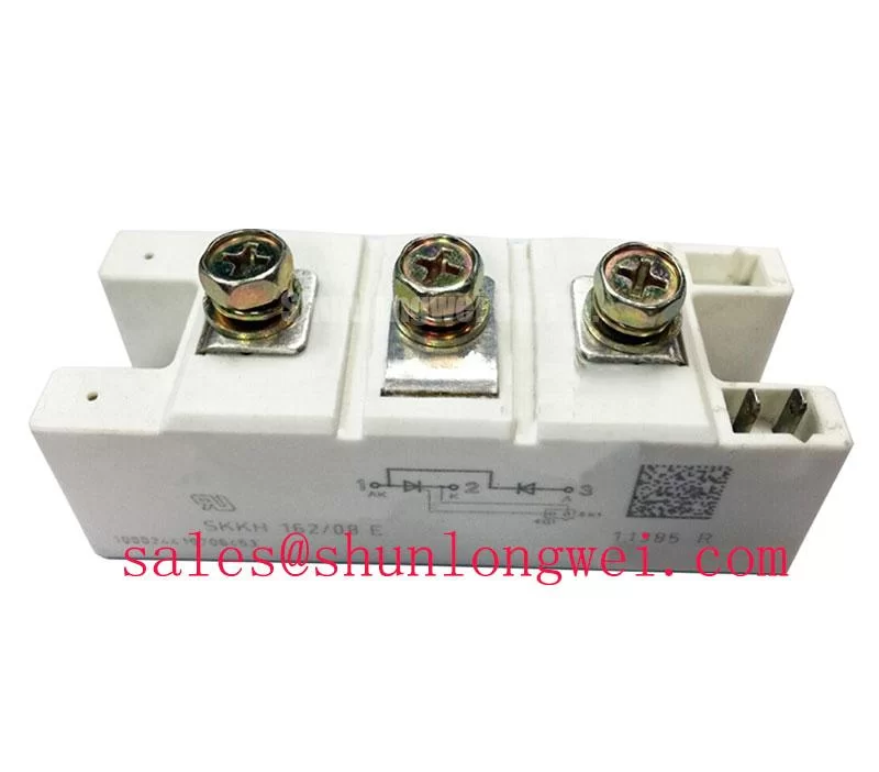
With the SVC cabinet isolated, check the module’s marked diode polarity and measure each power path with a calibrated multimeter before applying control power. Compare the cold-state readings with a known-good unit, then confirm that the installed part is the Semikron SKKD162/08 in the SEMIPACK 2, Case A 23 package. Its official repetitive peak reverse voltage is 800 V, while its mean forward current is 160 A at Tcase = 95°C.
The factory electrical limits should remain visible in the replacement record: maximum forward voltage is 1.5 V at IF = 500 A and Tvj = 25°C, surge forward current is 6000 A for 10 ms at Tvj = 25°C, and the specified I²t value is 180,000 A²s for 10 ms at Tvj = 25°C. The operating junction temperature range is −40 to +135°C. Isolation is specified at 3000 V~ for 1 minute. These are Official Specification values, not calculated operating allowances.
💡 Bench Tip: Use ESD precautions, keep the module unpowered and discharged, and record the cold forward-test result before comparing it with a replacement device.
Transient Dynamics & Electrical Design: High-Frequency Switching Loss Dissipation on SKKD162/08
In a grid-tied static Var compensator or thyristor-switched capacitor branch, inspect the commutation path rather than judging the module from nominal current alone. The SKKD162/08 data confirms forward voltage and surge capability, but reverse-recovery peak current, recovery time, and soft-recovery behavior must be taken from the applicable device documentation or measured in the complete circuit. They should not be inferred from the 800 V rating.
During commissioning, review the semiconductor fuse coordination using the module’s official 180,000 A²s value and the fuse manufacturer’s let-through curve. The protection study should account for prospective fault current, clearing time, wiring impedance, and the actual capacitor-bank topology. A fuse selected only by RMS current may not provide suitable short-circuit coordination. The 6000 A surge forward current for 10 ms is a specified surge reference, not permission to operate repeatedly at that condition.
Keep the high-current terminal connections short, clean, and mechanically secure. Confirm that each cable is landed on the correct marked terminal and that busbar pressure does not twist the SEMIPACK case. Gate-drive wiring, where the surrounding SVC topology uses controlled thyristor devices, should be routed separately from high di/dt power conductors. IGT, VGT, pulse duration, and pulse-train requirements belong to the selected thyristor and firing circuit; they must be checked from the relevant data rather than assigned to this diode module.
For background on the product family, consult Semikron SEMIPACK Thyristor / Diode Modules. The related Semikron CAL Diode Technology reference can also help engineers separate published diode technology information from system-level switching assumptions.
Field Diagnostics & Commissioning: RC Snubber Network Optimization to Prevent False Turn-On
RC snubber selection should begin with the measured switching waveform at the module terminals. Observe voltage overshoot, ringing, and capacitor-bank commutation behavior with a suitable differential probe, then adjust the network only after checking probe connection, busbar layout, and the firing sequence. The objective is to control unwanted dv/dt and localized di/dt stress without creating excessive snubber current or resistor heating.
Series saturable reactors may be considered in branches where the initial current rise is difficult to control, but their suitability depends on pulse energy, reset conditions, switching frequency, and the complete SVC design. The SKKD162/08 provides the published surge and I²t references needed for protection coordination; it does not define an RC value or reactor specification. The system engineer should validate the final network under the highest expected capacitor voltage and switching repetition.
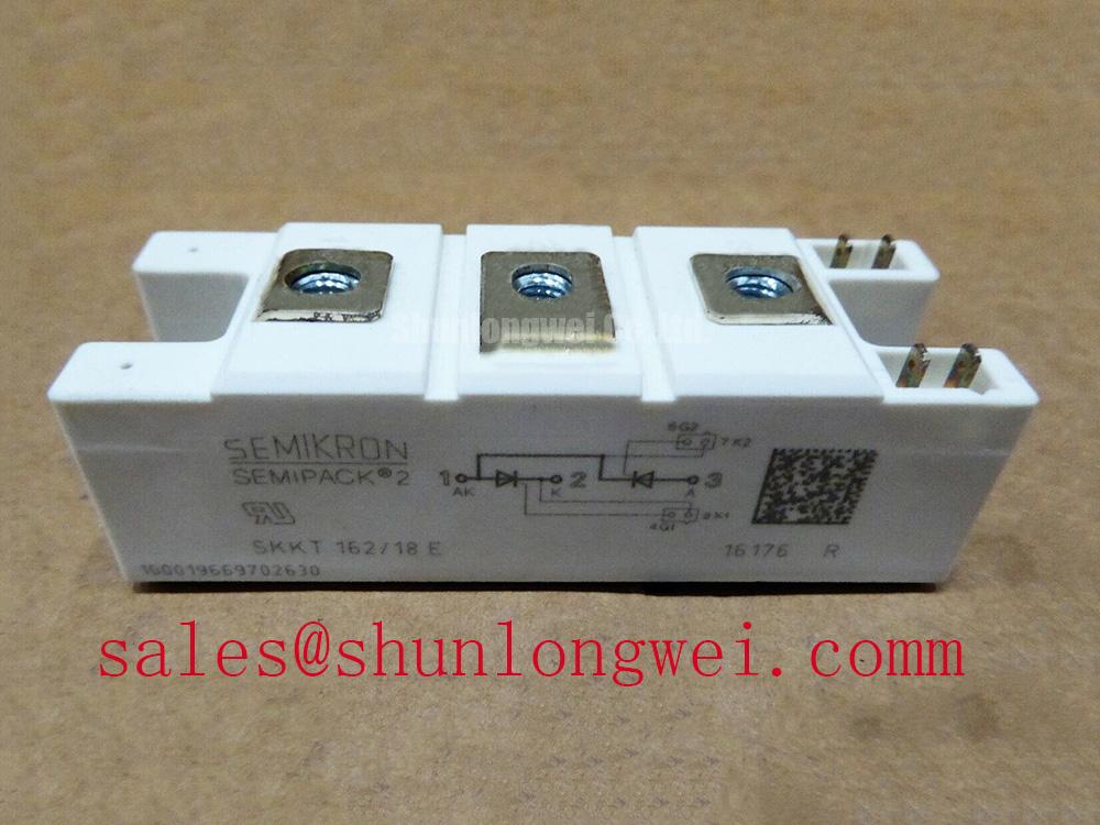
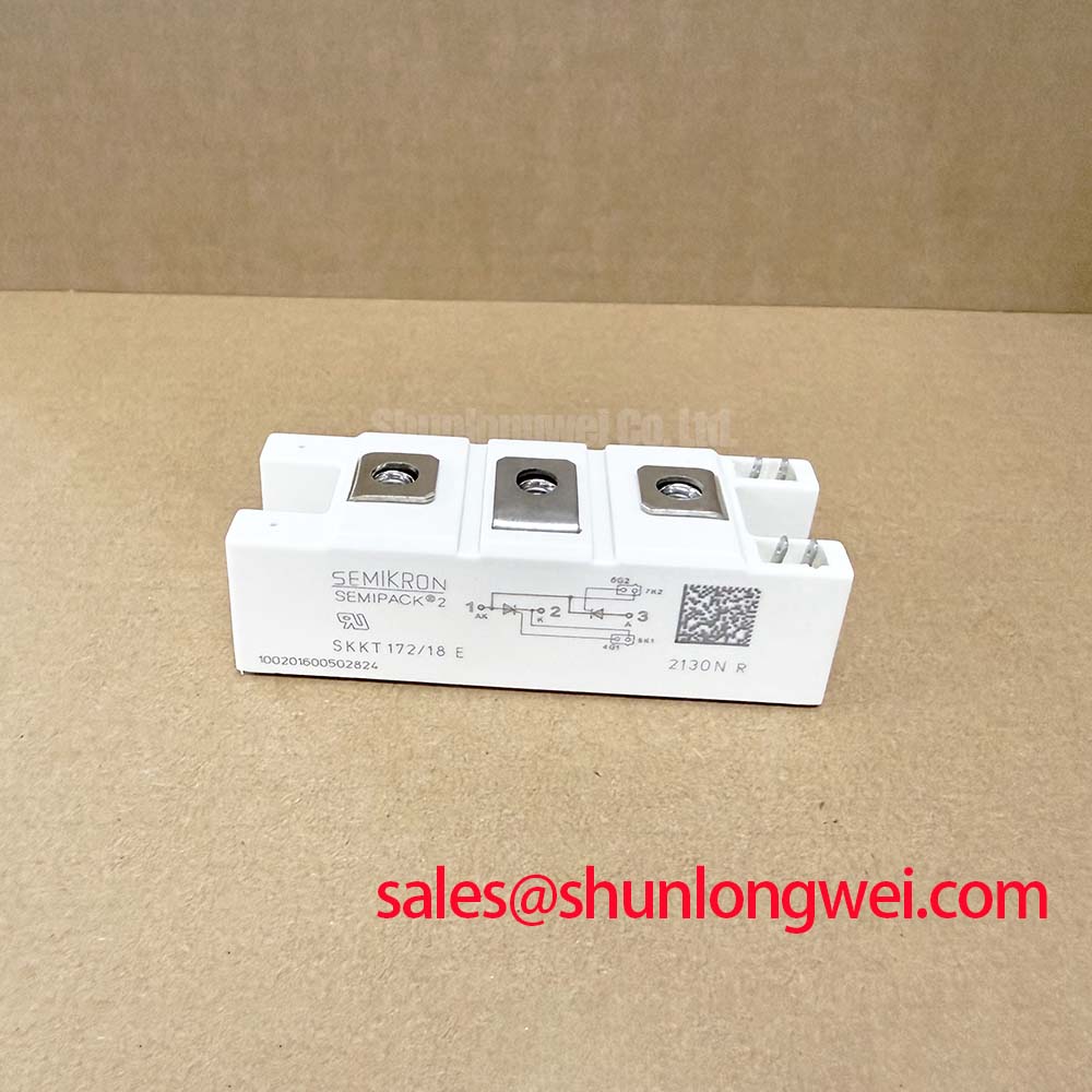
When the replacement is part of a broader rectifier and switching assembly, engineers may evaluate the electrically related SKKT200-18E as a separate front-end or auxiliary-stage device. It should not be treated as an automatic substitute for the SKKD162/08 because voltage, current, circuit function, terminal arrangement, and thermal conditions must all match.
Transient Dynamics & Electrical Design: Baseplate Thermal Resistance on SKKD162/08
Thermal commissioning should focus on uniform contact between the module base and heatsink. The official junction-to-case thermal resistance is 0.18 °C/W per diode. Use this value with the actual loss distribution, heatsink thermal resistance, airflow, ambient temperature, and duty cycle when checking junction-temperature margin. A temperature rise at one side of the case can point to uneven contact pressure, contamination, mounting distortion, or unequal current sharing in the external buswork.
Clean both mating surfaces according to the equipment maintenance procedure and spread the approved thermal interface material evenly. Use the manufacturer’s specified mounting hardware and tightening sequence; do not substitute a generic torque value for the device installation instruction. After assembly, inspect for case rocking, displaced washers, damaged threads, or a heatsink surface that prevents full contact. Thermal imaging during a controlled load test can identify hot regions, but emissivity and surface finish should be accounted for before interpreting absolute temperature.
The 3000 V~ one-minute isolation specification supports an insulation review, but the complete cabinet still depends on creepage, clearance, contamination level, busbar geometry, and enclosure conditions. Confirm the finished assembly with the applicable safety procedure and avoid applying a test voltage through connected control electronics. For broader guidance on parasitic inductance, snubber behavior, and power-system test planning, see Mastering Power System Dynamics.
For cross-reference evaluation, the related SKKH91-18E belongs to a different device configuration and should be assessed only against the original schematic, terminal markings, electrical ratings, and thermal interface requirements.