

Content last revised on September 26, 2026
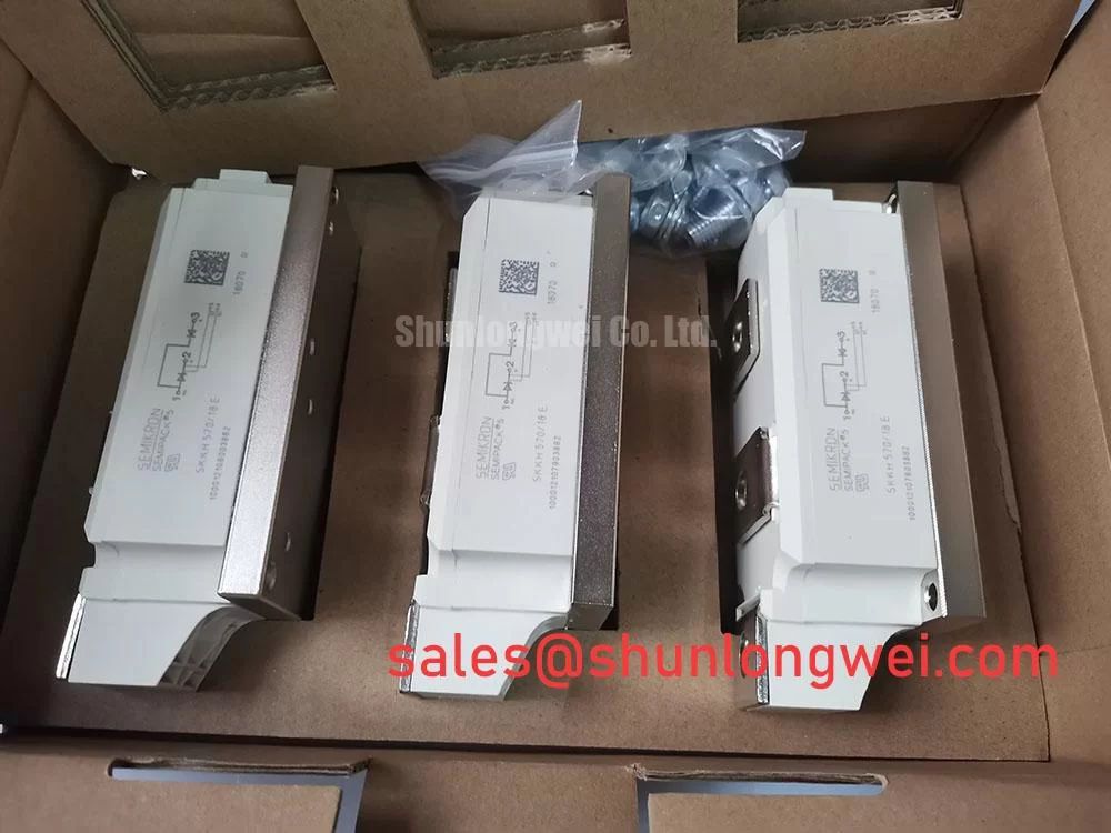
Preventing Spurious Faults: Thermal Stress during High-Peak Events for SKKH 570/18 E
For a thyristor module installed in an SVC or thyristor switched capacitor branch, the first maintenance task is to confirm that the actual current waveform and line conditions remain within the device and system protection design. The official 1800 V rating is a key identification parameter, but it is not a substitute for reviewing repetitive voltage, non-repetitive surge current, commutation conditions, and recovery behavior in the applicable Semikron documentation.
High peak current events should be investigated with the complete protection record rather than by replacing the module immediately. Review the semiconductor fuse specification, the manufacturer’s I²t coordination information, the clearing time, and the prospective fault current of the installation. The correct fuse relationship is system dependent. If the available fuse table does not correspond to the installed branch, the protection engineer should obtain the appropriate data before energization.
Thermal stress can also accumulate when a cooling path is restricted. Inspect the heat sink surface, airflow path, cabinet filters, and nearby buswork for signs of overheating. Check that the module baseplate sits evenly on the heat sink and that the fasteners follow the equipment manufacturer’s stated tightening sequence and torque. No mounting torque value should be assumed from the part number alone.
In a high voltage reactive power cabinet, voltage reapplication after a current zero deserves particular attention. Designers should verify the measured transient waveform with suitable isolated instrumentation and compare the result with the approved voltage and dv/dt limits for the exact circuit. The external resonant topology reference can help technicians understand how switching paths and parasitic energy affect semiconductor stress, but the final protection settings must come from the equipment design.
Maintenance Note: Monitor contact temperature during scheduled operation and recheck heat sink cleanliness, airflow, and terminal tightness after any thermal alarm or cabinet service.
Field Diagnostics & Commissioning: Baseplate Thermal Resistance in SKKH 570/18 E Topologies
Commissioning should begin with a de energized visual inspection and a record of the original conductor arrangement. Photograph the busbar orientation, gate wiring, auxiliary connections, and heat sink interface before removal. A replacement module may have the same external category while still requiring verification of terminal identity, polarity, firing circuit compatibility, and mechanical clearances in the host assembly.
The baseplate and heat sink interface are central to thermal performance. Remove old thermal material according to the site maintenance procedure, clean both mating surfaces without scratching them, and inspect for raised areas, foreign particles, or uneven contact marks. Apply only the thermal interface material and application method approved for the equipment. Excess compound, incomplete coverage, or uneven clamping can increase thermal resistance and create localized temperature differences across the module.
When measuring thermal behavior, compare the repaired branch with a known good phase under equivalent load and switching conditions. Record heat sink inlet conditions, cabinet airflow, terminal temperature, and the temperature trend during the operating cycle. A difference between phases does not identify one single fault by itself; it may require inspection of current sharing, connection resistance, firing symmetry, heat sink contact, or sensor placement.
The official package designation is Semipack, while the supplied product data does not include a numerical baseplate thermal resistance value. The system integrator should therefore confirm the applicable Rth(j-c), allowable case temperature, mounting instructions, and thermal interface requirements from the original device documentation before calculating a heat sink requirement.
Terminal work should be completed with the circuit isolated, discharged, and proven dead. Inspect copper faces for oxidation and confirm that flexible conductors are not applying mechanical force to the module terminals. After reassembly, perform a controlled insulation and continuity assessment appropriate to the equipment voltage class, followed by low energy functional checks before full power is restored.
Where the control and power stages use related Semikron devices, engineers may review the neutral product context for SKKH273/18E. This is an information link rather than a substitute recommendation; interchangeability must be established from the circuit diagram, electrical ratings, package details, and the original bill of materials.
SKKH 570/18 E Circuit Protection & Reliability: Calibrating Dynamic Voltage Sharing and RC Damping
RC snubbers and series reactors should be assessed as part of the complete commutation network. Their purpose may include limiting transient voltage, controlling dv/dt, reducing unwanted triggering, and managing current rise in the semiconductor branch. The suitable R and C values cannot be assigned from the model number because they depend on line impedance, capacitor bank characteristics, busbar geometry, switching frequency, expected fault energy, and the measured transient waveform.
Use an approved differential voltage probe and current measurement method to observe the switching event at the module terminals. Minimize the measurement loop and validate the instrument bandwidth before interpreting a spike. Designers should reduce parasitic busbar loop inductance where practical to suppress turn off overshoot, then verify the peak voltage against the equipment DC or AC operating boundary during controlled switching tests.
Dynamic voltage sharing is especially important where several semiconductor paths operate in one power cabinet. Check the physical symmetry of conductors, the condition of laminated or parallel busbars, and the distance between snubber connections and the module terminals. A visually similar cable route can produce a different transient response if its return path changes. Any saturable reactor selection should be supported by the system short circuit study and the required current waveform, not by a generic replacement value.
Fuse coordination must be reviewed together with the semiconductor’s surge capability and the capacitor bank’s stored energy. The applicable Semikron fuse I²t table should be matched to the precise fuse family and installation conditions. If the table, fuse label, and equipment drawing disagree, suspend the high energy test and resolve the documentation gap before proceeding.
For maintenance troubleshooting, compare gate to cathode signals at the module terminals rather than only at the controller output. A missing or distorted pulse may result from wiring, isolation, connector condition, firing transformer behavior, or control timing. An abnormal voltage waveform may indicate an impedance or commutation issue, so it should be compared with a known good signal path using an oscilloscope and the approved safety procedure.
Assembly Integrity & Layout Architecture: Implementing Gate Protection for SKKH 570/18 E
The firing circuit must be evaluated against the thyristor gate requirements stated in the applicable Semikron documentation. Confirm gate current, gate voltage, pulse duration, pulse repetition, and back porch behavior from the original control design rather than importing values from another thyristor family. A pulse train can improve firing reliability in some systems, but the gate transformer, isolation barrier, driver capacity, and thermal conditions must all be verified together.
Inspect the gate and cathode conductors for excessive length, loose crimping, damaged insulation, and routing alongside high di/dt power conductors. Keep the control return path defined by the equipment design and separate it from noisy power current paths where the layout permits. The objective is to prevent false triggering and uneven firing while preserving the required isolation and creepage arrangement.
In installations with parallel current paths, positive temperature coefficient behavior can support static current sharing, but it does not guarantee equal dynamic sharing during a fast transient. Designers should verify conductor symmetry, firing pulse timing, thermal coupling, and current waveform balance with the actual assembly. Any imbalance should be investigated through measurement rather than assigned to the module alone.
Before final energization, confirm the module identity, the 1800 V official rated voltage, the 570 A official rated current, and the Semipack mechanical interface against the equipment records. Verify all terminals, protective devices, heat sink contact, and firing connections independently. The related SKKT91/08D page may be used for neutral comparison during a parts review, but the maintenance team should not treat it as an automatic substitute without electrical and mechanical approval.
After the cold checks, use a staged startup with current and voltage monitoring at the approved test points. Watch for unequal phase temperature, unexpected reactive current, unstable firing, and abnormal acoustic or electrical behavior. Record the commissioning observations so future maintenance staff can distinguish a normal installation signature from a developing connection, cooling, or control problem.