





Content last revised on October 1, 2026
Assembly Integrity & Layout Architecture: Evaluating Reverse Recovery for SKKT-570-18-E
| Manufacturer | Semikron |
|---|---|
| Part Number | SKKT-570-18-E |
| Product Category | Thyristor/Thyristor Module |
| Rated Voltage | 1800 V |
| Rated Current | 570 A |
| Package | Semipack |
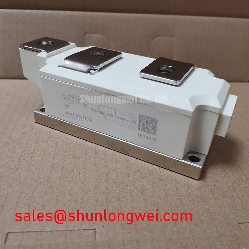
Measure the installed phase terminals for unintended continuity to the heat sink and compare each power path with the original service unit before energizing the soft starter. The SKKT-570-18-E is a 1800 V, 570 A Semikron thyristor/thyristor module in a Semipack package; these are primary electrical identity points for replacement screening.
Reverse recovery behavior must be evaluated from the applicable Semikron electrical data rather than inferred from the current rating alone. During a controlled commutation test, capture the reverse current peak, recovery interval, and voltage overshoot at the module terminals. The purpose is to assess switching loss, commutation stress, and conducted or radiated interference in the complete bridge. The official Semikron SEMIPACK® thyristor and diode module reference provides product-family context.
Keep the high-current loop compact and symmetrical where the original equipment layout permits. Verify the fuse coordination and I²t values from the matching manufacturer table before selecting or reusing semiconductor fuses. Do not substitute a fuse solely because its continuous current appears similar. Terminal hardware, busbar flatness, contact pressure, and the manufacturer’s specified tightening procedure should be checked against the original mechanical documentation.
Preventing Spurious Faults: Thermal Duty Cycle Management and Bypass Control for SKKT-570-18-E
Check the bypass contactor timing, phase-control firing sequence, and motor current waveform while the starter transitions from controlled acceleration to bypass operation. A three-phase motor solid-state soft starter can expose the power module to repeated thermal cycles when firing is unbalanced, bypass transfer is delayed, or the motor repeatedly restarts.
The stated 570 A rating is a product parameter, not a universal operating-current allowance for every enclosure or duty cycle. Designers should verify the actual RMS phase current, overload profile, ambient temperature, heatsink performance, and permissible junction-temperature conditions for the complete assembly. Locked-rotor current reduction must be demonstrated through the motor and starter control settings; the module rating does not establish a universal reduction target.
Inspect each terminal for discoloration, looseness, oxide contamination, or uneven busbar seating. Thermal imaging during a representative start sequence can help locate abnormal phase imbalance, but temperature findings should be correlated with current measurements and the known-good phases. Maintain creepage and clearance around the power terminals according to the applicable equipment insulation design and working-voltage requirements. An MOV network may be evaluated as part of the equipment-level transient protection strategy, with its voltage, energy, and coordination selected by the system designer.
Maintenance Note: Monitor terminal and heatsink temperature during scheduled service, clean the cooling path, and inspect the thermal interface for drying, pump-out, or uneven contact before returning the starter to duty.
Benchtop Waveform Tuning: Mitigating Commutation Stress with RC Damping on SKKT-570-18-E
Probe the module terminals and gate-control reference during a no-load switching test, then compare turn-on timing across all phases. An oscilloscope check can reveal asymmetric firing, excessive commutation overshoot, or ringing that a static resistance test cannot identify.
RC snubber networks should be treated as an Engineering Recommendation, with resistor and capacitor values determined from the measured parasitic inductance, switching waveform, leakage behavior, and the applicable thyristor data. The objective is to limit unwanted dv/dt triggering and reduce transient voltage stress without creating excessive snubber current or resistor dissipation. Do not assume that a network used on another Semipack assembly is suitable for this device.
Verify whether the original terminal arrangement includes any auxiliary sensing or control connection. Do not assume a Kelvin-emitter terminal on this thyristor module; route control references according to the actual Semikron terminal drawing and keep them separate from high-current commutation paths. Where a saturable reactor or additional series impedance is used, its effect should be confirmed through current-rise and voltage-waveform measurements under the real load conditions.
For replacement planning, verify the candidate device’s voltage, current, terminal, thermal, and gate-control requirements. A thyristor/diode module should not be treated as an automatic substitute for this thyristor/thyristor module.
SKKT-570-18-E Operational Boundaries: Evaluating Post-Surge Reverse Voltage Blocking
After a suspected surge, isolate the equipment, verify that hazardous voltages have dissipated, and measure the affected phase path against the other phases before applying reverse voltage again. Record visible package damage, terminal discoloration, insulation condition, and the resistance trend from a properly isolated test setup; a single resistance reading cannot establish full blocking capability.
Post-surge assessment should use the applicable ITSM, surge-duration, junction-temperature, and reverse-blocking limits from the official Semikron documentation for this exact device. The 1800 V voltage rating and 570 A current rating do not, by themselves, establish surge-current or fuse I²t limits.
Recheck the snubber, MOV, line reactor, fuse, and grounding path after any overvoltage event. The protection network should be reviewed as a coordinated system because a failed MOV, incorrect fuse class, poor bonding connection, or excessive wiring inductance can alter the stress seen by the module. System engineers should verify peak voltage margins during controlled switching tests before restoring service. The broader selection principles are discussed in the Power Semiconductor Selection Guide.