

Content last revised on October 26, 2026
SKD146/16 Circuit Protection & Reliability
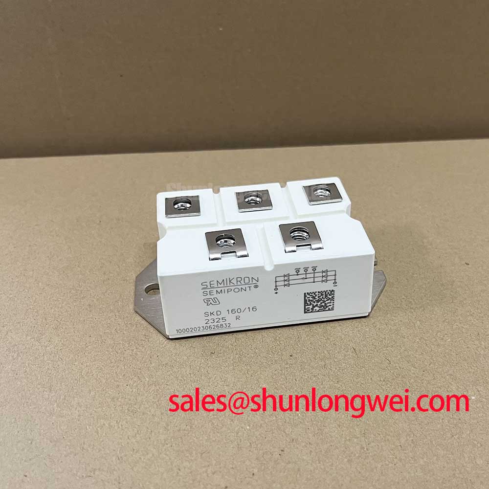
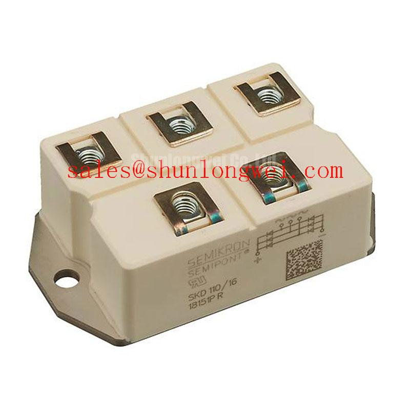
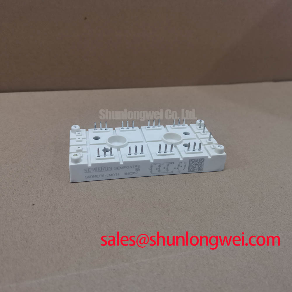
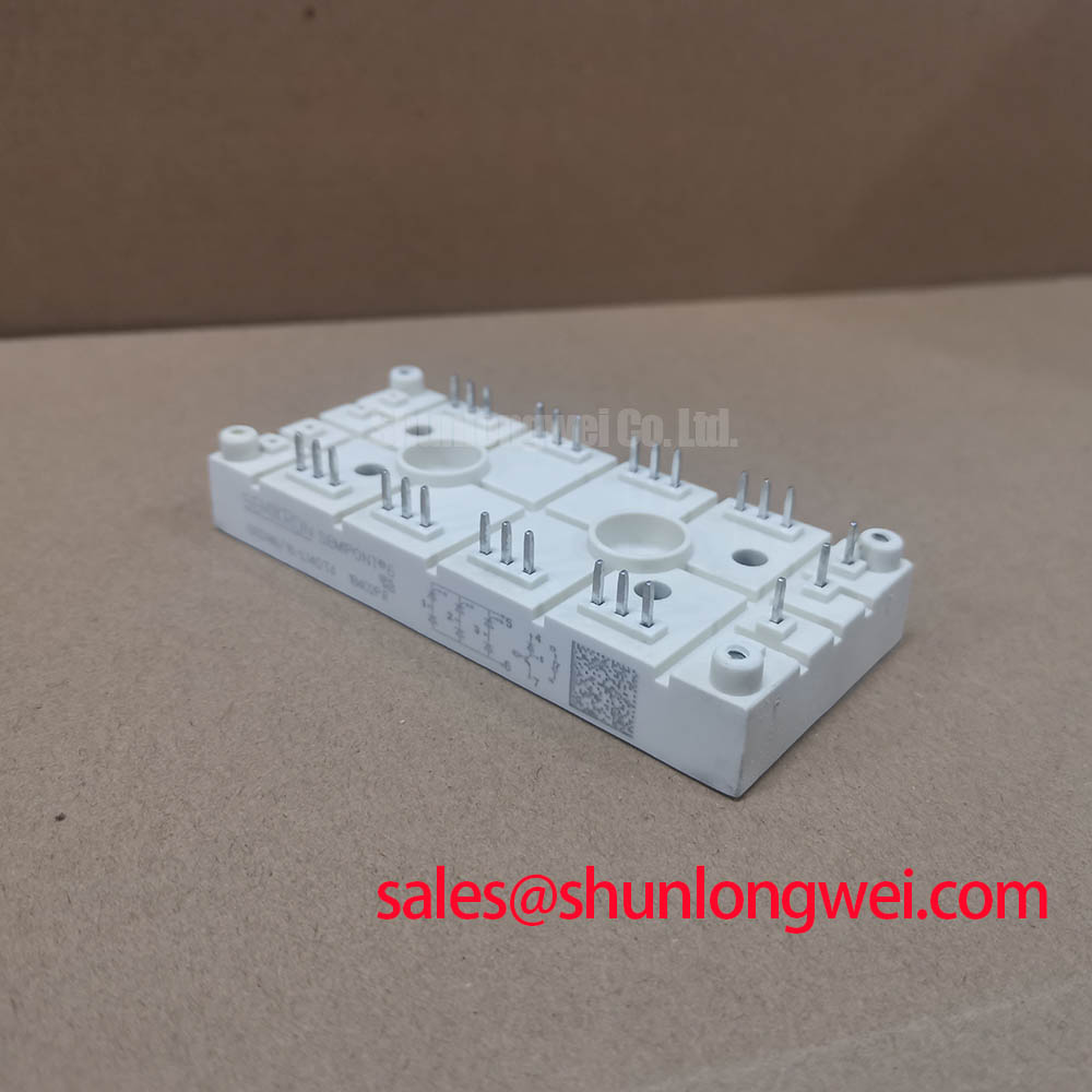
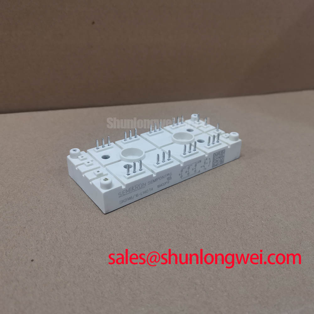
Disconnect the SKD146/16 from external current paths, verify that stored energy has been discharged, and map its terminal markings against the equipment schematic before taking diode-mode readings. Check corresponding rectifier paths in both polarities, recording instrument settings and module temperature. Unequal readings warrant further investigation; a handheld meter does not establish rated-current performance or reverse-voltage withstand.
The Semikron SKD146/16 is a bridge rectifier module, not a gate-controlled thyristor module or an IGBT. That distinction matters when reviewing a repair specification: gate-trigger current, holding current, and firing-angle commands are not control parameters for this diode bridge.
Remove gate-trigger calibration from the SKD146/16 acceptance checklist and concentrate on rectifier polarity, reverse blocking, and fault-current coordination. A gate-pulse rise-time requirement belongs to a separately identified controlled device, not this bridge. Terminal identification should follow the module connection drawing rather than an assumed arrangement based on another package.
Official Specification: repetitive peak reverse voltage is 1600 V; average forward current is 146 A at a case temperature of 85 °C; surge forward current is 1500 A for 10 ms. Preserve those conditions in the inspection record. The surge rating describes a specified transient capability, not an allowable repetitive overload.
Design Consideration: coordinate the protective fuse using the applicable module surge conditions, its permissible I²t data, and the fuse manufacturer’s clearing characteristics. The 1500 A headline alone does not establish a fuse selection. Assess prospective fault current and interruption conditions within the actual assembly, including the influence of upstream protection.
The 2500 V AC isolation rating for 1 minute is an Official Specification and is separate from reverse blocking across the rectifier junctions. It is not a continuous working-voltage declaration for the complete equipment. Engineering Recommendation: any insulation test should follow an approved procedure that defines the tested terminals, baseplate connection, instrument settings, and treatment of connected electronics.
💡 Bench Tip: Discharge the DC link and isolate parallel circuit paths before comparing cold diode-mode readings with a known-good module.
SKD146/16 Thermal-Electrical Optimization: Conduction Losses and Cooling
Separate low-current bench measurements from the forward-conduction model used for thermal assessment. The Official Specification gives a threshold voltage of 0.85 V and forward slope resistance of 1.5 mΩ. These are conduction-model parameters; neither defines a universal diode-mode pass reading.
The Official Specification places operating junction temperature between −40 and +150 °C. Design Consideration: evaluate heat removal from actual rectified-current waveforms, case temperature, and the installed cooling arrangement. Inspect mounting-surface condition, contact uniformity, and terminal alignment. Apply the model-specific mounting and terminal torque instructions rather than borrowing values from a similar-looking module.
For replacement screening, the linked SKB52-08 should be treated as a separate comparison candidate, not a verified direct replacement. The following comparison identifies the evidence required before an interchange decision.
| Selection checkpoint | SKD146/16 | SKB52-08 |
|---|---|---|
| Repetitive peak reverse voltage | 1600 V — Official Specification | Consult datasheet |
| Average forward current | 146 A at Tc = 85 °C — Official Specification | Compare rating and temperature condition |
| Surge forward current | 1500 A for 10 ms — Official Specification | Compare waveform and duration |
| Mechanical and terminal compatibility | Match connection drawing and mounting interface | Verify independently before substitution |
Design Consideration: reverse-recovery current and recovery time depend on test conditions and cannot be inferred from these static ratings. During system validation, correlate commutation current with terminal-voltage overshoot. Minimize unnecessary commutation-loop area to reduce parasitic-inductance effects, with conductor geometry and suppression measures determined by measured operating stresses.
SKD146/16 System Integration: Rectification Versus Firing-Angle Control
Trace any firing-angle command to the controlled switching stage rather than assigning it to the SKD146/16. A diode bridge conducts according to applied terminal voltages and circuit conditions; it does not accept a programmable firing delay. Gate-loop damping, pulse trains, and trigger-current calibration therefore belong to the separately specified thyristor circuit.
When evaluating a grid-tied static var compensator or thyristor-switched capacitor assembly, designers should establish whether this bridge serves an auxiliary rectification function before assessing compatibility. The SKD116/18-L75 can be reviewed separately when comparing another rectifier-stage requirement; its presence in a related product range does not establish electrical or mechanical interchangeability.
Engineering Recommendation: use the Semikron-Danfoss official hub for manufacturer documentation and assembly guidance. The manufacturer’s MiniSKiiP power-module information concerns a separate product platform and should not supply mounting assumptions for this bridge.
For equipment containing an adjacent inverter, The Ultimate IGBT Knowledge Base provides complementary switching-stage background, not an SKD146/16 acceptance standard. Keep the bridge test record tied to terminal polarity, measured conduction-path consistency, cooling-interface condition, and protection coordination before reconnecting it to the assembly.