Content last revised on September 27, 2026
Preventing Spurious Faults: Ensuring Uniform Heatsink Contact Pressure Guidelines for SKB 30/12 A1
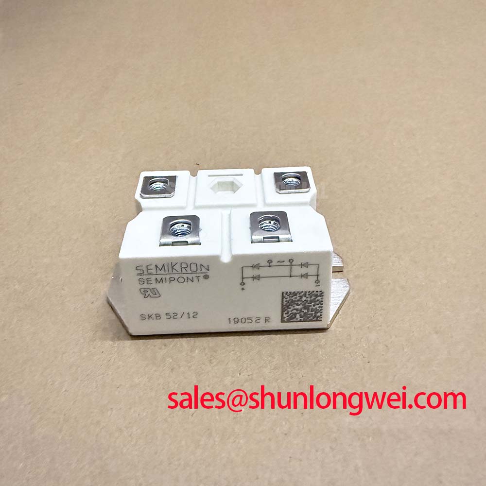
With the equipment isolated, check the SKB 30/12 A1 terminal markings against the original wiring diagram before testing its diode paths or removing it from the heatsink. This Semikron bridge rectifier module is specified for 1200 V repetitive peak reverse voltage and 36 A DC output current at a case temperature of 80°C. Those ratings establish useful screening boundaries, but they do not establish the module’s suitability for every circuit that contains a motor soft starter.
The published thermal figure supplied for this model is 0.15 K/W junction-to-heatsink thermal resistance per diode (Official Specification). It is not a junction-to-case value, and it should not be treated as a measurement of an installed assembly with an uneven mounting surface. During a repair, inspect the heatsink contact area and the module’s mating surface for raised debris, old interface material, and signs of uneven seating. Apply thermal interface material according to the applicable assembly instructions, then check that the module sits flat as its fasteners are tightened.
Uniform contact matters because the current rating is tied to temperature: 36 A at Tc = 80°C (Official Specification). A current reading alone therefore cannot confirm thermal suitability. As a Design Consideration, compare operating temperature at repeatable load conditions with the equipment’s known-good behavior and investigate a change in contact pattern before attributing an unexpected temperature rise to the semiconductor. The provided specifications do not state a mounting torque or fastener size, so obtain those details from the original module documentation and equipment assembly procedure rather than assigning a generic torque to this part.
The module has a specified 3000 V~ isolation voltage (Official Specification). That figure must not be used on its own to declare a completed installation compliant with an insulation standard. As a Design Consideration, check terminal spacing, creepage paths, enclosure clearances, and the equipment’s required insulation test procedure after reassembly. These are system-level checks, particularly where conductive contamination or displaced wiring could compromise an otherwise sound installation.
Assessing Fuse Coordination and Surge Stress on SKB 30/12 A1
The specified 300 A surge forward current for 10 ms (Official Specification) describes a short-duration device rating. It is not a published device I²t withstand value, and it cannot establish that a particular fuse will prevent damage during a dead short. Fuse coordination requires the selected fuse’s total clearing I²t under the prospective fault conditions and a compatible withstand limit from the original module documentation. Neither a device I²t limit nor a fuse coordination table is present in the supplied model data, so a guaranteed damage-free fault outcome cannot be calculated from the figures on this page.
| Coordination item | Available SKB 30/12 A1 information | Required system check |
|---|---|---|
| Repetitive reverse-voltage boundary | 1200 V VRRM (Official Specification) | Measure or establish the worst-case reverse voltage at the module terminals. |
| DC output current boundary | 36 A at Tc = 80°C (Official Specification) | Assess operating current together with case temperature and cooling conditions. |
| Short-duration surge boundary | 300 A IFSM for 10 ms (Official Specification) | Compare the actual fault waveform and protective-device behavior with documented device limits. |
| Fuse and device I²t coordination | No device I²t value supplied | Obtain the module’s applicable withstand data and the selected fuse’s total clearing data. |
On the bench, review the rectifier connection in the equipment schematic before interpreting voltage and current traces. A current surge during energization, a sustained overload, and a short circuit call for different assessments; the 300 A rating does not make them interchangeable. As a Design Consideration, keep voltage-sense and current-probe references consistent between suspect and known-good measurements. If an overvoltage absorber is fitted in the surrounding circuit, assess it as part of that circuit’s measured transient behavior rather than assuming a MOV or TVS alone protects the bridge. The overview of transient-voltage-suppression diodes explains the general clamping mechanism, not a protection rating for this module.
Checking Diode Paths Instead of Gate Trigger Current on SKB 30/12 A1
SKB 30/12 A1 is a diode bridge rectifier module, not a gate-triggered thyristor module. There is consequently no gate trigger current, gate-pulse rise-time requirement, back-porch current, or multi-pulse firing scheme to tune for this part. Applying thyristor gate criteria to its terminals would misdirect the fault investigation. Check the equipment schematic to distinguish the bridge’s rectification function from any separately fitted SCRs in a soft starter.
For this module, a useful cold-state check is to compare diode paths with the documented terminal diagram and the meter’s stated test behavior. Record both test polarities, then investigate readings that differ from a known-good assembly without treating any single meter value as a definitive failure diagnosis. In an energized system, inspect the bridge’s input and output waveforms alongside the load and protective circuitry; the source, wiring, and connected components can all affect what appears at the module terminals.
The specified typical forward voltage is 1.05 V at IF = 30 A and Tj = 25°C (Official Specification). This is a defined operating-point measurement, not a pass threshold for a handheld meter at an unspecified test current. Semiconductor characteristics also differ across device technologies. Semikron Danfoss’s bare-die technology information provides broader diode context, but should not be substituted for the SKB 30/12 A1 terminal diagram or ratings.
SKB 30/12 A1 Circuit Protection & Reliability: Assessing AC-to-DC Waveforms
A firing-angle sweep does not describe the SKB 30/12 A1 itself: its diodes conduct according to circuit voltage and current conditions, without a controllable firing angle. In a high-voltage three-phase motor solid-state soft starter, engineers should first identify whether a bridge of this type is present in an auxiliary supply or another documented subsystem. They should not infer from the equipment name that the bridge belongs in the motor’s main controlled-power path.
For an installed bridge, compare measured AC input and DC output waveforms against the original circuit documentation under the relevant load conditions. Rectified output, ripple, and input current depend on the source and connected load; the supplied module ratings do not define a universal AC-to-DC transfer curve, power factor, or reactive-power value. If the equipment uses separately controlled power devices, assess their firing-angle behavior in that separate circuit. This distinction keeps a soft-starter control problem from being incorrectly assigned to a passive rectifier.
When evaluating another bridge for a repair, compare the schematic function, terminal arrangement, mechanical fit, isolation requirements, voltage rating, current rating at its stated thermal condition, surge data, and available protection-coordination information. The SKD 25/14 is a separate model worth examining against those criteria, not an established drop-in replacement for the SKB 30/12 A1. Pro Tip: Keep measurement and power-return paths orderly so transient readings can be checked at the module terminals without mistaking wiring effects for device behavior.
Where the wider equipment also contains switched power semiconductors, the discussion in The 1200 V CoolSiC™ MOSFET Advantage in Three offers background on a different device technology; its switching guidance and ratings should not be assigned to this diode bridge. For the rectifier, finish the assessment against its documented 1200 V VRRM, 36 A at Tc = 80°C, thermal interface condition, and the voltages actually measured in the equipment.