Content last revised on September 20, 2026
SKKH132/08E Operational Boundaries: Evaluating Turn-On Current Rise Limiting: Preventing Excessive Current Rise
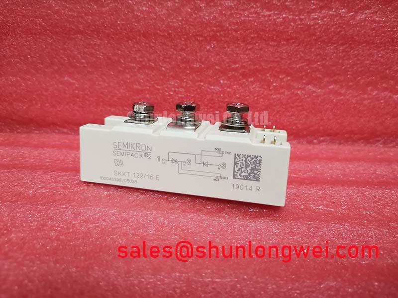
Before reconnecting a removed power assembly, verify the nameplate against the replacement record, inspect the Semipack housing and terminals for heat discoloration or mechanical damage, and compare the circuit connections with the original equipment schematic. The SKKH132/08E is a Semikron thyristor/diode module rated at 800 V and 132 A, supplied in a Semipack package. These are Official Datasheet Specifications and define the electrical identity that must be retained during maintenance assessment.
For phase-control circuits, capacitor-switching stages, and regenerative energy paths, turn-on current rise is determined by the complete commutation circuit rather than by the module rating alone. The system designer should inspect the source impedance, transformer leakage behavior, capacitor-bank connection sequence, busbar geometry, semiconductor fuse coordination, and the status of any series reactor before applying gate pulses. A saturable reactor or other current-limiting element can influence early current rise, but its suitability must be verified against the actual transient waveform and the protected equipment's operating sequence.
RC snubber networks are commonly evaluated where rapid voltage transitions could create unintended thyristor triggering. This is a Design Consideration, not an official claim that a particular snubber value is required for SKKH132/08E. Snubber capacitance, resistance, dissipation capability, and placement should be determined from measured commutation behavior, expected source transients, and the voltage margin observed at the module terminals.
Gate triggering also needs to be considered as a circuit-level function. Engineers should confirm the original gate-drive pulse train, isolation method, return path, and triggering conditions from the equipment documentation. A pulse train may be used in controlled rectifier or capacitor-switching equipment to improve triggering consistency across operating conditions, but gate current and gate voltage settings must follow the applicable Semikron documentation and the installed control-board design.
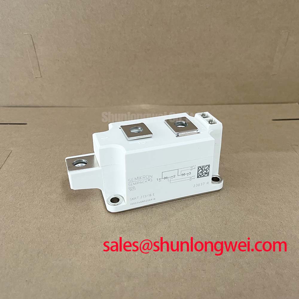
When evaluating a grid-tied static var compensator or thyristor-switched capacitor stage, verify that the replacement module has the required circuit function and terminal arrangement before considering its voltage and current ratings. The SKKH273/18E can be reviewed as a related Semikron module during an engineering comparison, although its application must be validated against the original schematic, thermal path, mechanical interface, and protection coordination.
Assembly Integrity & Layout Architecture: Implementing Surge Energy Dissipation and Clamping Voltage for SKKH132/08E
The physical route from the incoming AC terminals to SKKH132/08E should be reviewed before a failed assembly is energized. Loose terminal interfaces, long conductor loops, unequal busbar paths, and degraded snubber connections can change the transient conditions experienced by an otherwise correctly rated 800 V module. Confirm terminal identity from the original module documentation and equipment schematic instead of inferring a connection sequence from package position alone.
Metal oxide varistors and RC stages are generally evaluated as complementary protection elements in industrial AC input and commutation circuits. Their clamping behavior, energy capability, fuse arrangement, and failure mode belong to the system protection design. Where surge immunity is being assessed against IEC 61000-4-5 test conditions, the equipment-level protection network should be tested as an assembly. A power module does not independently establish complete equipment surge or EMC compliance.
Busbar architecture has direct value during high-current commutation. A compact, symmetrical path reduces unequal current distribution and parasitic inductance that can contribute to terminal voltage excursions. This is particularly relevant in thyristor-switched capacitor equipment, where the capacitor bank, reactor, fuse, snubber, and semiconductor module operate as one transient system. Engineers should capture voltage and current waveforms during representative switching events and compare the measured peak conditions with the applicable device and system limits.
Pro Tip: De-energize, isolate, and verify stored-energy discharge before disturbing capacitor-bank cables or module terminals, because residual charge can remain outside the semiconductor assembly.
For related rectifier or commutation architecture, the SKKH330/08E may be relevant for neutral evaluation within the wider power-stage bill of materials. It should not be treated as a predetermined substitute without checking circuit topology, voltage class, current duty, gate-drive interface, terminal configuration, and cooling conditions.
Semikron's SEMIPACK thyristor and diode module information provides useful product-family context when reviewing package-level installation and power-semiconductor application requirements.
SKKH132/08E Circuit Protection & Reliability: Calibrating Short-Circuit Withstand Limits: Coordination
A dead-short review should begin with the actual protective chain: upstream source capability, branch conductors, semiconductor fuse type, fuse mounting, contact resistance, and clearing characteristics. The SKKH132/08E official ratings of 800 V and 132 A do not, by themselves, define a permitted fault-clearing energy for a particular installation. The applicable product datasheet and fuse manufacturer documentation must be used together when determining whether a protection arrangement is coordinated.
Semiconductor fuse coordination is an Engineering Calculation when the fault current, prospective clearing behavior, and the relevant device withstand data have been established from authoritative documentation. The fuse's pre-arcing and total clearing I2t data must be interpreted for the actual circuit voltage and fault scenario. Do not assume that a conventional line fuse provides equivalent semiconductor protection, and do not infer a module withstand value from its continuous current rating.
Maintenance teams should inspect failed protection hardware without forcing a single-cause diagnosis. A cleared fuse can result from a semiconductor fault, a downstream bus fault, abnormal capacitor switching, insulation breakdown elsewhere in the cabinet, or a control-sequence issue. Measure the power path, inspect the snubber and MOV network, examine control-board isolation behavior, and validate the gate pulse timing against a known-good equipment state where available.
Industrial drive and compensation control boards often use optocouplers or digital isolators between low-voltage logic and power-side gate circuitry. Common-mode transient immunity is a system property involving isolation components, PCB layout, return paths, supply decoupling, and transient conditions. Designers should verify that switching events do not disturb the intended triggering state through oscilloscope measurements made with suitable high-voltage differential and isolated probing methods.
Longer-term thermal behavior also depends on the assembly around the module, including heatsink condition, airflow or liquid-cooling performance, loading profile, and switching duty. For context on evolving thermal-management approaches, see The Advanced Thermal Management Revolution. That technical discussion should be used as background, while SKKH132/08E installation decisions remain subject to its own documentation and the equipment-level validation plan.
Preventing Spurious Faults: Mechanical Mounting Torque Sequence and Thermal Guidelines for SKKH132/08E
Clean the heatsink interface, inspect it for raised damage or embedded debris, and confirm that the SKKH132/08E mounting surface sits flat before tightening any hardware. Uneven contact pressure can produce a localized thermal path problem even when electrical connections appear correct. The module's Semipack package should be mounted using the hardware arrangement and tightening requirements specified in the applicable Semikron documentation.
Mounting torque is a Design Consideration unless it is taken directly from the official module drawing or datasheet for this exact package revision. Follow the documented tightening sequence, apply fasteners progressively to avoid distorting the baseplate, and use a calibrated tool. The system integrator should verify interface flatness, thermal compound application method, heatsink material condition, and contact-pressure uniformity as part of the assembly process.
Thermal resistance from junction to case is an official device characteristic only when read from the correct SKKH132/08E documentation and associated test conditions. It should not be replaced by a generic package estimate. The case-to-heatsink portion of the thermal path is determined by the installed surface, interface material, mounting force, and mechanical condition. During recommissioning, measure temperatures at repeatable locations under controlled load and investigate meaningful differences between comparable phases or parallel assemblies.
Where the module is used in a grid-tied static var compensator or thyristor-switched capacitor cabinet, technicians should also inspect airflow paths, cabinet contamination, busbar support spacing, and terminal security. These checks help identify installation conditions that may affect electrical stress or thermal transfer without assigning a fault to one component prematurely.
For diode-related technology context relevant to high-power semiconductor behavior, Semikron's CAL diode technology information is a useful external reference. Final acceptance should remain based on the original circuit requirements, official SKKH132/08E specifications, measured waveforms, protection coordination, and the equipment manufacturer's service procedure.