
Content last revised on September 14, 2026
SKKH330/08E Circuit Protection & Reliability: Calibrating AC Line Surge Immunity and Lightning Transients
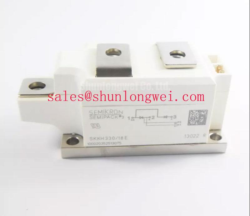
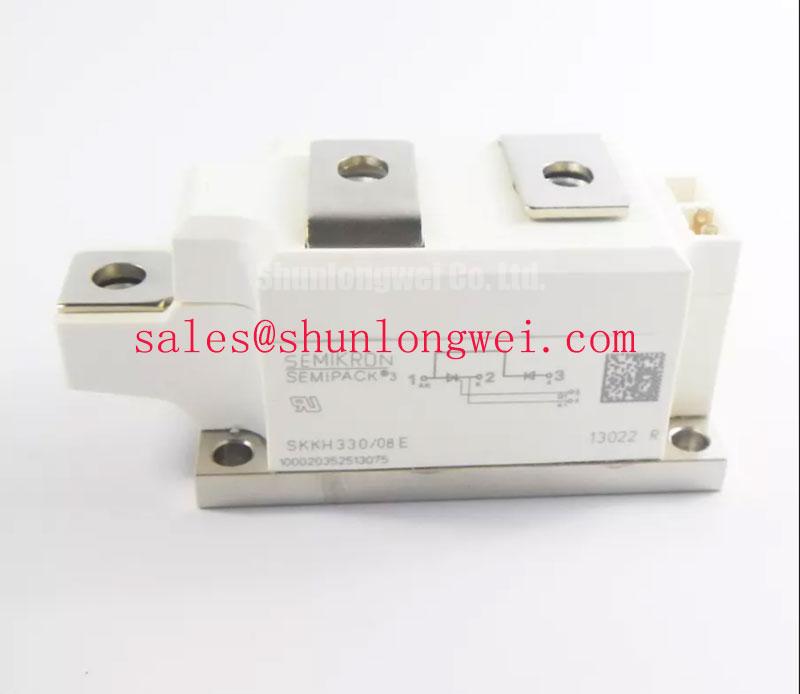
With the supply isolated, begin by matching the terminal markings and circuit position to the equipment schematic, then compare cold diode mode readings with a known serviceable assembly where available. SKKH330/08E is a Semikron thyristor and diode module with an official repetitive peak reverse voltage rating of 800 V and a maximum average on state current of 305 A at case temperature 85°C. This rating combination is relevant when assessing replacement modules in the power path of a high voltage three phase motor solid state soft starter, provided the original circuit topology, firing circuit, cooling arrangement, and terminal assignment remain verified by the system integrator.
| Official Datasheet Specification | Value | Condition |
|---|---|---|
| Repetitive peak reverse voltage, VRRM | 800 V | Official rating |
| Maximum average on state current, ITAV | 305 A | Case temperature 85°C |
| Surge on state current, ITSM | 8000 A | 10 ms, junction temperature 125°C |
| Junction to case thermal resistance | 0.116°C/W | Per thyristor |
| Threshold voltage, VT(TO) | 0.80 V | Junction temperature 125°C |
| On state slope resistance, rT | 0.60 mΩ | Junction temperature 125°C |
| Critical off state voltage rise, dv/dt | 1000 V/μs | Official rating |
| Module weight | Approximately 600 g | Module only |
Check the installed line protection before attributing a failed soft starter power stage to the module itself. The 800 V VRRM rating is an Official Datasheet Specification defining the repetitive reverse voltage boundary of the SKKH330/08E. It does not establish that the surrounding starter cabinet will withstand a particular surge level, lightning exposure, insulation test, or EMC requirement. Those are system level outcomes determined by the incoming supply, enclosure, wiring, earthing, protective devices, and validation method.
As a Design Consideration, inspect the condition, connection integrity, and specified ratings of any metal oxide varistors and RC suppression networks installed ahead of the semiconductor paths. MOV selection must be coordinated with the actual AC line voltage, temporary overvoltage conditions, protective coordination, and the surge test requirement applied to the complete equipment. Surge immunity testing is commonly discussed under IEC 61000 4 5 at equipment level; it should not be represented as a standalone certification of this module.
Fuse coordination also requires the original equipment documentation. The module is officially specified for an 8000 A surge on state current for 10 ms at Tvj 125°C, but this short duration value is not a substitute for fuse selection data. Compare the fuse manufacturer’s pre arcing and clearing characteristics with the prospective fault current, the circuit configuration, and the applicable semiconductor protection guidance. Where the original soft starter uses purpose selected semiconductor fuses, retain the documented coordination approach rather than treating the ITSM figure as an independently usable fuse I²t rating.
For product family context, Semikron describes its SEMIPACK® thyristor and diode modules as power semiconductor modules used across controlled power conversion duties. Terminal polarity and gate connections must still be verified against the drawing for the exact installed circuit.
Assembly Integrity & Layout Architecture: Implementing Turn On Current Rise Limiting for SKKH330/08E
Before reassembly, clean the heatsink interface and inspect the module base contact area for debris, corrosion residue, or mechanical distortion that could prevent even thermal contact. The stated junction to case thermal resistance is 0.116°C/W per thyristor, an Official Datasheet Specification. The actual junction temperature in a soft starter also depends on interface condition, heatsink performance, conduction waveform, airflow, cabinet temperature, and the firing angle used during motor starting.
💡 Bench Tip: De energize and discharge the power assembly before moving gate or power leads, then record cold diode mode readings and terminal positions before disconnecting the original module.
Use only the module mounting torque and tightening sequence specified by the applicable mechanical documentation. If those values are not available in the service documents, the system integrator should obtain them from the relevant manufacturer material rather than applying a generic torque value. This is a Design Consideration because excessive or uneven clamping can affect mounting integrity, while insufficient clamping can increase thermal interface resistance.
RC snubbers and series current limiting elements should be examined as connected circuit parts, not assumed to be optional accessories. The module’s official critical off state voltage rise rating is 1000 V/μs. A snubber network can help control voltage transition behavior at the thyristor terminals, while a suitable series reactor can moderate current rise where the system commutation conditions require it. Values must be determined from measured circuit behavior, source impedance, wiring inductance, capacitor tolerance, resistor pulse capability, and the intended firing sequence.
Keep gate return paths and high current paths arranged to minimize unwanted coupling. During commissioning, verify terminal waveforms against the applicable voltage boundary and inspect for unintended triggering under line disturbance conditions. A gate pulse issue, inadequate suppression, or a layout induced transient can each contribute to irregular firing behavior, so oscilloscope measurements should be interpreted with the known good control path and the original schematic.
Transient Dynamics & Electrical Design: Reverse Recovery Charge on SKKH330/08E
Do not assign a reverse recovery charge, reverse recovery peak current, or recovery time value to the SKKH330/08E unless it is taken from the exact applicable manufacturer datasheet revision. Those parameters are not included in the official specifications provided here. In a thyristor and diode module circuit, recovery behavior can influence commutation stress, current overlap, switching loss distribution, and conducted or radiated disturbance, but the magnitude must be assessed from verified device data and measured operating conditions.
A practical inspection begins with the control sequence and the location of the diode path in the original soft starter schematic. Confirm which terminals are intended to conduct during each half cycle and whether the installed protection network remains electrically continuous. A basic multimeter diode mode test can reveal an obvious abnormal short or open path, but it cannot characterize high current recovery behavior or confirm dynamic suitability under operating voltage.
As an Engineering Recommendation, capture voltage and current waveforms with measurement equipment appropriate for the voltage category and bandwidth of the equipment under test. Review switching events at the module terminals, with particular attention to commutation intervals and repetitive peaks. The objective is to verify that actual peaks remain within the system’s validated operating boundaries, rather than inferring dynamic performance from static readings.
Where an alternate module is being evaluated after a documented engineering review, the SKKH273/18E can be considered as a separate Semikron module reference. Voltage class, current duty, terminal arrangement, thermal conditions, triggering requirements, and circuit behavior must be compared directly; no interchangeability is implied by product family naming alone.
SKKH330/08E Thermal Electrical Optimization: Power Factor Degradation and Harmonic Mitigation Practical Tuning
For an AC motor soft starter, firing angle control changes the applied motor voltage during the start profile. This changes RMS current, displacement effects, harmonic content, and thermal loading across the power stage. The SKKH330/08E on state model includes an official threshold voltage of 0.80 V at Tvj 125°C and an official on state slope resistance of 0.60 mΩ at Tvj 125°C. These values support conduction loss estimation at the stated junction temperature condition, but they do not define the complete system power factor or harmonic performance.
When evaluating a firing range from near zero degrees toward high delay angles, engineers should review measured line current, motor current, supply voltage distortion, bypass contactor operation where fitted, and heatsink temperature. Long operation at heavily delayed firing can alter both electrical and thermal duty. The acceptable start ramp, current limit behavior, and bypass transfer point are system determined settings that should remain aligned with the original starter control documentation and motor load requirements.
Thermal verification should focus on the complete heat path from junction to case, thermal interface, heatsink, and surrounding air. A thin, continuous thermal interface layer and uniform mechanical contact are general Design Considerations, while the required material type and application process should follow the equipment service procedure. For broader cooling concepts, see The Advanced Thermal Management Revolution.
If a starter shows unstable ramping, elevated heatsink temperature, or irregular line current, inspect the firing command, sensing feedback, suppression components, cooling path, motor cable condition, and supply quality as separate evidence paths. The module’s approximate 600 g weight should also be considered during service handling so that unsupported terminals and gate connections are not mechanically loaded during installation.