Content last revised on June 5, 2026
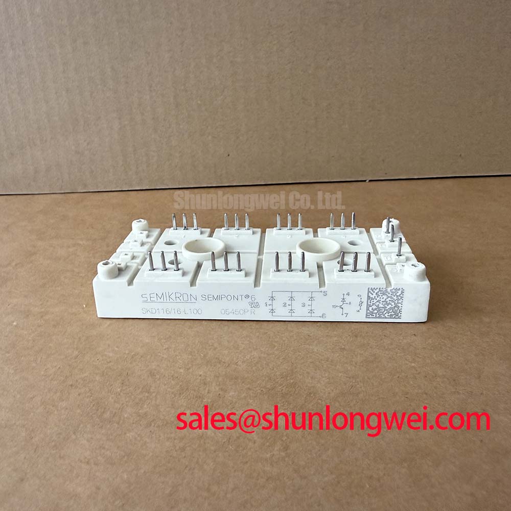
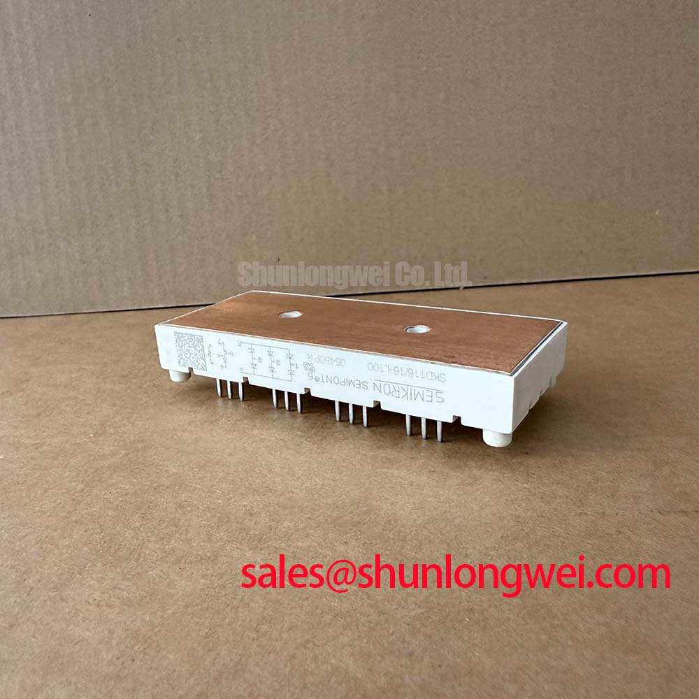
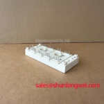
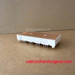
High-Voltage Rectification Performance: The SKD116/16-L100 1600V 116A Three-Phase Bridge
Superior Thermal Cycling and Surge Resilience for Heavy-Duty Industrial Rectification
For power electronics engineers requiring stable DC bus voltages from industrial AC supplies, the SKD116/16-L100 provides a ruggedized 1600V 116A solution. This module is characterized by its 1600V maximum repetitive peak reverse voltage and a continuous output current of 116A, supported by a massive surge current rating of 1150A. The high I2t rating of 6600 A2s ensures the module survives input transients that would compromise lesser components. To answer the implicit design concern regarding safety margins: the 1600V rating offers a robust buffer for 480V grid applications, significantly reducing the risk of avalanche breakdown during line voltage spikes. For industrial drives prioritizing thermal margin and input reliability, the SKD116/16-L100 is the optimal choice for the input stage.
Application Scenarios & Value
Achieving System-Level Benefits in High-Power Industrial Drives
Engineers often face the challenge of managing input rectifier heat in compact motor drive housings where airflow is constrained. The SKD116/16-L100 addresses this directly with its high thermal conductivity isolated baseplate. In a Variable Frequency Drive (VFD), this module serves as the critical primary stage, converting three-phase AC into a stable DC link voltage. The module's low forward voltage drop, typically 1.4V at 150A, minimizes conductive losses, directly contributing to higher overall system efficiency and reduced cooling requirements.
In high-capacity Uninterruptible Power Supply (UPS) systems, the SKD116/16-L100 handles the rectification stage where reliability against grid fluctuations is non-negotiable. Its robust mechanical construction is designed to withstand the rigors of heavy industry, including Welding Power Supply units where high-frequency noise and thermal cycling are constant. For systems requiring even higher current handling, the SKKD162/16 offers a Vces of 1600V with increased current capacity. Conversely, for highly integrated designs where space is at a premium, the SKIIP32NAB12T49 provides a Power Integrated Module (PIM) topology that combines rectification and inverter stages.
Technical & Design Deep Dive
A Closer Look at Thermal Management and Isolation Engineering
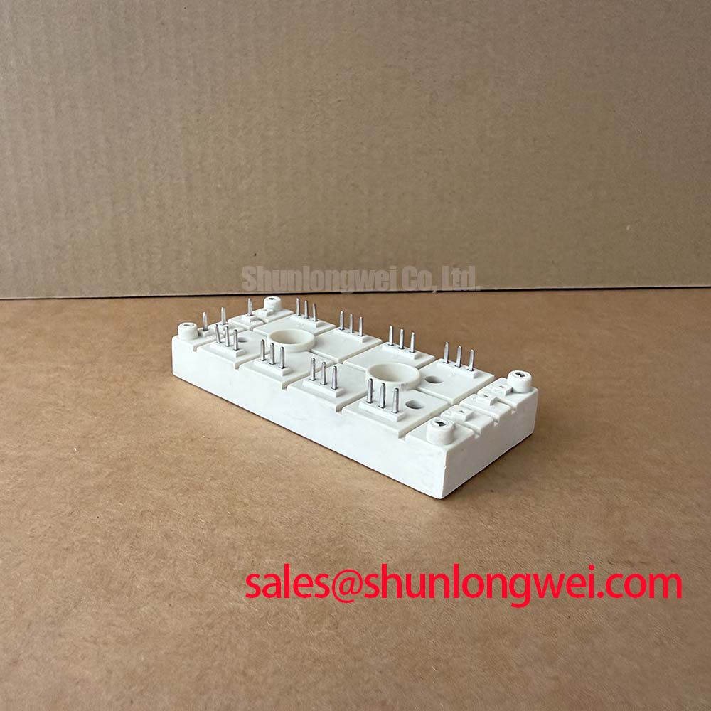
The SKD116/16-L100 utilizes the SEMIPONT 3 package, a benchmark in the industry for mechanical stability. One of the defining features is its isolated metal baseplate, which utilizes a sophisticated ceramic insulator. To interpret the engineering significance of the Rth(j-c) value of 0.35 K/W: think of this thermal resistance as a wide thermal drain, pulling heat away from the silicon junction with minimal obstruction. This allows the module to maintain a higher current density without exceeding its 150°C maximum junction temperature.
Furthermore, the surge current rating (IFSM) acts like an electrical airbag; while it is not intended for continuous operation, the 1150A capability is what prevents catastrophic module failure during short-circuit events or major grid inrushes. This resilience is essential for meeting IEC 61800-3 EMC standards and ensuring the longevity of the downstream DC bus capacitors by providing a stable rectified output. Understanding these nuances is part of decoding IGBT datasheets and related power modules to ensure long-term field reliability.
Key Parameter Overview
Decoding the Specs for Enhanced Industrial Reliability
The following technical specifications define the operating boundaries and performance potential of the SKD116/16-L100 three-phase bridge rectifier module.
| Symbol | Parameter Description | Value (Typical/Max) |
|---|---|---|
| VRRM | Max. Repetitive Peak Reverse Voltage | 1600 V |
| ID | Maximum DC Output Current (Tc=100°C) | 116 A |
| IFSM | Peak Forward Surge Current (10ms, 25°C) | 1150 A |
| VF | Maximum Forward Voltage (IF=150A) | 1.4 V |
| I2t | Rating for Fusing (10ms) | 6600 A2s |
| Visol | Isolation Voltage (AC, 1 min) | 3000 V |
| Rth(j-c) | Thermal Resistance (per diode) | 0.35 K/W |
Download the SKD116/16-L100 datasheet for detailed specifications and performance curves.
Frequently Asked Questions
- How does the Rth(j-c) of 0.35 K/W directly impact heatsink selection and overall system power density?
The 0.35 K/W thermal resistance determines the maximum allowable temperature rise from the baseplate to the junction. A lower resistance allows for a smaller heatsink for the same current load, or higher current output for a fixed heatsink size, thereby enabling higher power density in the overall cabinet design. - Is the 1600V VRRM rating necessary for a standard 400V or 480V AC input?
Yes. In industrial environments, line transients and inductive kickback can easily exceed 1000V. A 1600V rating provides a safety margin that ensures the module remains within its Safe Operating Area, preventing premature failure due to overvoltage stress. - What are the primary benefits of the L100 package in harsh environments?
The L100 package features a robust screw-terminal interface and an isolated baseplate that simplifies mounting and improves vibration resistance. This is critical for Marine LCDs and heavy industrial equipment where mechanical shocks are frequent. - How do I test the SKD116/16-L100 module using a standard digital multimeter?
You can perform a diode check between the AC input terminals and the DC output terminals. A healthy module will show a standard forward voltage drop (approx. 0.4V to 0.7V depending on the meter's current) and an open circuit in reverse for all six internal diodes. For more details, see our guide on how to test an IGBT module with a multimeter, as the principles for diode bridges are largely identical.
Strategic procurement of power components like the SKD116/16-L100 requires a balance between raw electrical specifications and long-term thermal reliability. As industrial systems move toward higher efficiency and more compact footprints, the ability of a rectifier module to handle both steady-state thermal loads and transient surge events becomes the deciding factor in system uptime. Integrating such modules into a comprehensive design framework—leveraging resources like the engineer's ultimate guide—ensures that the final power stage meets the rigorous demands of modern automation and energy conversion standards.