Content last revised on September 22, 2026
SKKT330/14E Circuit Protection & Reliability
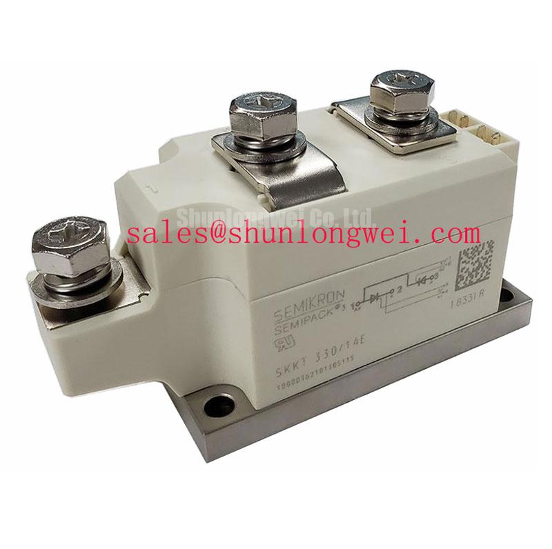
Before reconnecting a replacement power module, isolate the converter, inspect the Semipack housing and baseplate, and verify the installed circuit’s voltage and current requirements against the marked device data. The SKKT330/14E is a Semikron thyristor/diode module with a specified voltage rating of 1400 V, a rated current of 330 A, and a Semipack package designation.
These values identify the component category and its principal electrical rating, but they do not by themselves confirm suitability for every rectifier, controlled bridge, or induction heating power stage. The system integrator should verify the original circuit topology, line conditions, protection coordination, cooling arrangement, terminal assignment, and the complete manufacturer data sheet before energizing equipment.
In a medium-frequency induction melting or metal hardening power supply, the module is normally evaluated together with its heatsink, semiconductor fuses, busbars, gate or control wiring, and enclosure airflow. The official product data supplied for this product confirms the 1400 V voltage rating, 330 A current rating, and Semipack housing. Detailed thermal resistance, fuse coordination, I²t capability, mounting torque, and terminal connection values are not included in the supplied parameter set, so those figures must be taken from the applicable Semikron documentation for the exact revision.
Uniform contact between the module baseplate and heatsink is a Design Consideration rather than an assumed factory parameter. During service, clean both mating surfaces, check for burrs or distortion, and inspect the thermal interface material for uneven transfer. A concentrated imprint can indicate mechanical nonuniformity, while a dry or displaced area may require the interface method to be reviewed according to the approved assembly procedure. The purpose is to reduce local thermal resistance and avoid mechanical stress on the module body.
Fuse coordination should be checked against the prospective fault current and the semiconductor protection requirements stated in the relevant data sheet. Do not select a fuse solely from the module’s headline current rating. The fuse’s clearing behavior, available short-circuit current, coordination class, and the converter’s operating duty all affect the protection decision. The same principle applies to busbar connections: clean contact surfaces, adequate conductor support, and verified clamping are system responsibilities that cannot be inferred from the package name.
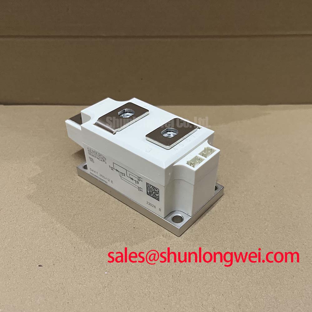
For a replacement in an existing assembly, record the original terminal arrangement before removing conductors. Compare the replacement footprint, polarity markings, control terminals, and mechanical interfaces with the equipment drawing. The SKKT 250/14E may be reviewed as a related Semikron reference model, but its ratings and physical interchangeability must be assessed independently rather than treated as an automatic substitute.
Maintenance Note: Isolate power before terminal work, and periodically inspect heatsink cleanliness, thermal interface condition, terminal tightness, and temperature rise under a known operating load.
Preventing Spurious Faults: Managing High-Peak Current Events in the SKKT330/14E
High peak current events in an induction heating rectifier can arise during startup, control transients, abnormal commutation, or a downstream fault. The correct review begins with the manufacturer’s surge-current and I²t data for the exact SKKT330/14E documentation. The supplied product information confirms the continuous headline ratings but does not specify the sinusoidal 10 ms half-cycle surge value, junction temperature limits, or reverse recovery data. Those values should not be reconstructed from the 330 A rating.
A Design Consideration for service engineers is to compare the recorded event with the complete protection chain. Review the input waveform, firing command, line impedance, DC-link behavior, fuse condition, and heatsink temperature history. A repeated protective trip may involve control timing, insufficient commutation margin, a damaged gate circuit, excessive wiring inductance, or an external load condition. It should not be assigned to a single internal failure without measurement.
Before reverse voltage is reapplied after a high-current event, verify that the control system has removed the relevant firing command and that the circuit has completed its intended commutation sequence. Oscilloscope measurements should use suitable differential probes and a safe measurement arrangement. Engineers should compare the observed voltage and current waveforms with the design limits in the applicable Semikron documentation, particularly where the module operates in a controlled rectifier or high-power heating converter.
Thermal inspection is also important after a peak event. Measure temperature consistently at the same mechanical location and under comparable load conditions. A rising contact temperature can suggest degraded thermal transfer, airflow restriction, loose mounting, or an overloaded operating point, but the measurement must be correlated with current, duty cycle, ambient temperature, and heatsink condition. No field lifetime, failure-rate, or avalanche-survival figure is assigned here because those values require an authoritative test source.
For equipment installed at altitude or in locations with unusual environmental exposure, the system designer should review insulation coordination, cooling derating, pollution level, condensation control, and the applicable installation standards. The module’s stated ratings do not independently establish a high-altitude cosmic-ray, single-event burnout, FIT, or insulation-reliability guarantee. Such assessments belong to the complete equipment design and require documented semiconductor and system-level evidence.
Transient Dynamics & Electrical Design: Dynamic Firing Delay Angle Adjustment for SKKT330/14E
In a phase-controlled AC-to-DC converter, changing the firing delay angle changes the average rectified output, input current displacement, reactive power demand, and the timing available for commutation. The range from approximately 0 degrees toward 150 degrees can therefore represent materially different operating conditions, but the exact transfer characteristic depends on the bridge topology, supply phase relationship, load type, overlap, control algorithm, and whether the converter operates as a rectifier or inverter.
The SKKT330/14E should be evaluated as the installed thyristor/diode module within that complete circuit. Its official supplied parameters are 1400 V, 330 A, and Semipack construction. They do not define the converter’s firing-angle range, power factor, reactive power, permissible commutation overlap, or control-loop response. Those characteristics must be calculated and validated from the system schematic and the full electrical data sheet.
When commissioning an induction melting or hardening supply, begin with a controlled low-energy test and confirm the phase sequence, gate pulse order, pulse isolation, and feedback polarity. Observe line current and device voltage while gradually changing the commanded firing angle. A mismatch between the expected and measured waveform may indicate incorrect gate timing, phase reference error, inadequate pulse transfer, commutation disturbance, or an external load response. Verify the signal path against a known-good channel before replacing the power module.
Power factor correction and harmonic performance should be reviewed at the equipment level. A thyristor bridge can draw a non-sinusoidal current even when the supply voltage is stable, and the impact depends on firing angle and load impedance. Designers should verify transformer heating, conductor temperature, capacitor interaction, and protection settings during the intended duty cycle. The module itself cannot be described as independently compliant with CISPR, EN 55011, or any complete-system EMC requirement.
Use the manufacturer’s terminal and gate connection information for the precise device revision. Do not assume that a visually similar Semipack device has identical control-terminal polarity or internal configuration. If the original documentation is unavailable, pause the installation and trace each power and control conductor from the circuit drawing rather than relying on color or position alone.
Assembly Integrity & Layout Architecture: Minimizing Commutation Turn-Off Voltage Spikes for SKKT330/14E
Commutation behavior is strongly affected by the complete current path. Busbar geometry, stray inductance, diode recovery, transformer leakage, snubber components, gate timing, and measurement-loop construction all influence the voltage observed during turn-off. The supplied product parameters do not include diode reverse-recovery current, reverse-recovery time, recovery softness factor, or a guaranteed EMI performance value for the SKKT330/14E. These characteristics must be confirmed from the applicable Semikron technical documentation or measured in the intended circuit.
A practical Design Consideration is to minimize unnecessary power-loop area while preserving creepage, clearance, service access, and mechanical support. Keep high-current conductors firmly supported and route control wiring away from rapidly changing power nodes. Any snubber or clamp network should be selected from measured switching behavior and verified for voltage, current, pulse energy, and temperature. The system engineer should confirm peak voltage margin against the converter’s DC and AC conditions during switching tests.
The external Semikron SEMIPACK® Thyristor / Diode Modules product information provides useful family-level context, while the manufacturer’s Semikron CAL Diode Technology information should not be treated as a substitute for the exact SKKT330/14E data sheet. Related technology descriptions cannot establish this model’s specific reverse-recovery waveform, insulation capability, or thermal performance.
For high-voltage assemblies, inspect creepage and clearance around terminals, busbars, insulating barriers, and contamination-prone surfaces. The required distances are determined by working voltage, overvoltage category, pollution degree, material group, altitude, and the applicable equipment standard. Do not assign a fixed spacing value to this module without completing that insulation-coordination review. Condensation and conductive dust can reduce practical insulation margins even when the mechanical layout appears acceptable.
Long-term maintenance records should include terminal inspection, heatsink condition, thermal measurements, waveform observations, fuse status, and any abnormal trip history. The Field Engineer’s Handbook can support a structured approach to testing and failure analysis, while the final acceptance criteria remain specific to the converter, its protection system, and the approved equipment documentation.