Content last revised on October 9, 2026
SKKT106-08E Thermal-Electrical Optimization: AC Input Transient Overvoltage Clamping and Practical Tuning
| Manufacturer | Semikron |
|---|---|
| Model | SKKT106-08E |
| Product category | Thyristor/Diode Module |
| Rated voltage | 800.0 V |
| Rated current | 106.0 A |
| Package | Semipack |
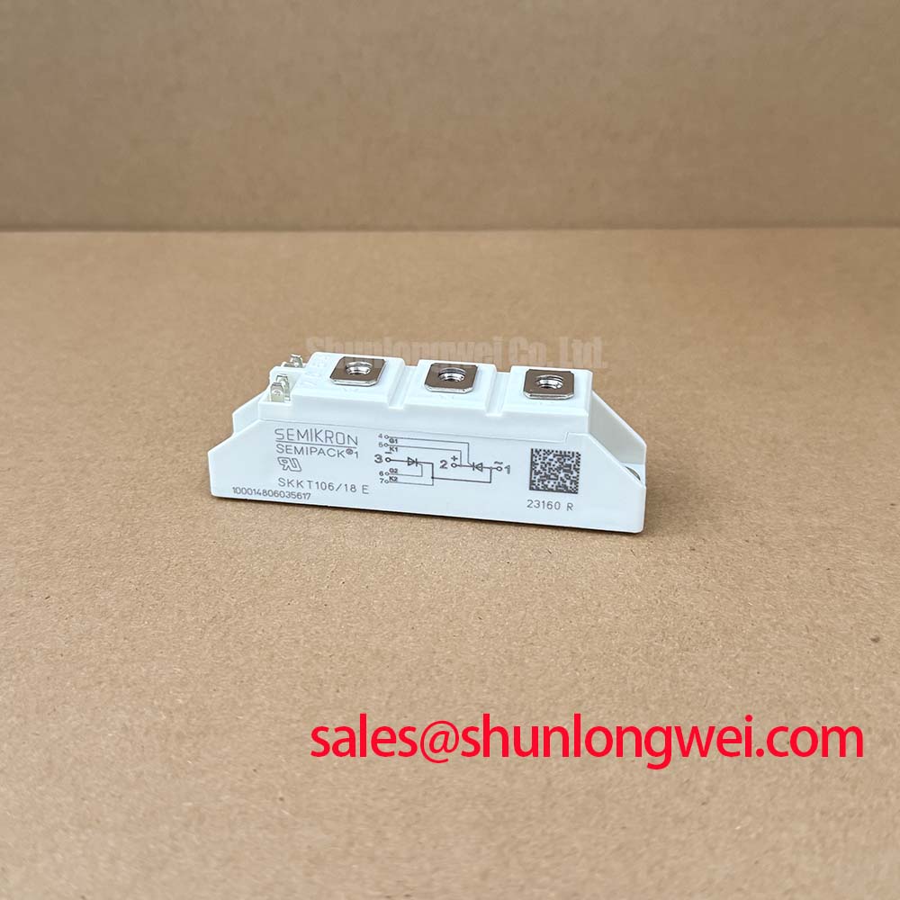
Check the three-phase soft starter’s surge protection path before energizing the replacement module: inspect the MOV arrangement, RC snubber placement, fuse coordination, and the physical routing between the protection network and the thyristor terminals. The SKKT106-08E is a Semikron Semipack thyristor/diode module rated at 800.0 V and 106.0 A, making those external protection decisions part of the installation assessment rather than characteristics that can be inferred from the product name.
For equipment exposed to AC line transients, the MOV must be selected against the actual line-to-line and line-to-earth surge arrangement, continuous operating voltage, clamping behavior, and available short-circuit current. The surge test level required by the finished soft starter should be assessed against the applicable installation environment and the relevant IEC 61000-4-5 test plan. An MOV is not a substitute for correctly coordinated fusing, and its failure mode must be considered alongside the module’s semiconductor protection.
Place the RC snubber with a short, low-inductance connection at the switching path it is intended to control. Designers should evaluate the snubber’s voltage rating, pulse energy, resistor impulse capability, and interaction with the motor’s power factor. Excessive capacitance can increase commutation current and losses, while insufficient damping can leave the thyristor exposed to unwanted transient voltage. Final values are system-determined and should be validated during controlled switching tests.
The fuse selection should be checked against the manufacturer’s published I2t coordination information and the prospective fault current of the starter. Do not replace the original fuse with a device chosen only by its continuous current marking. Confirm the terminal identification, busbar clearance, conductor orientation, and tightening procedure from the applicable Semikron installation documentation. The module’s mounting hardware should be tightened using the specified assembly torque for the actual hardware and heatsink arrangement.
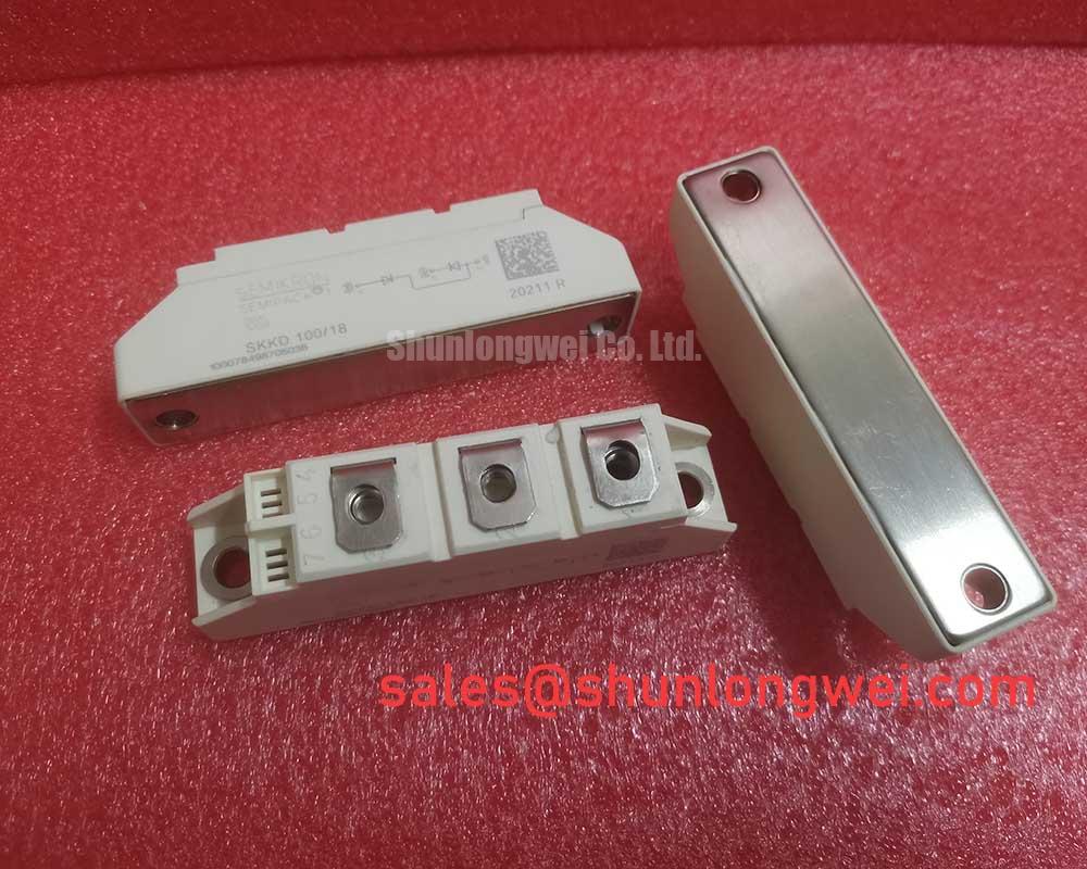
For package and product-line context, consult Semikron SEMIPACK® Thyristor / Diode Modules. The related SKKD 46/18 belongs to the same broad product family but has different electrical ratings; any substitution requires a full circuit, thermal, and protection review.
Field Diagnostics & Commissioning: Switching-Loss and Thermal Evaluation in SKKT106-08E Topologies
During commissioning, examine the switching waveform at the module terminals and compare the measured commutation behavior with the soft starter’s intended firing sequence. Reverse-recovery current and recovery time belong to the complete semiconductor and operating-condition assessment, including line current, junction temperature, commutation inductance, and gate timing. They should not be assumed from the 800.0 V voltage class or 106.0 A current rating alone.
Use a properly rated differential voltage probe and an appropriate current probe when checking turn-off stress, ringing, and electromagnetic interference. Probe loop area and grounding technique can otherwise create false overshoot indications. If the waveform shows excessive ringing, inspect the physical loop formed by the module, snubber, fuse, and AC bus before changing gate or snubber components. Minimize parasitic inductance in the power path, then verify peak voltage and current margins under the actual motor-starting load.
Thermal performance must be evaluated together with switching behavior. Confirm that the heatsink contact surface is clean and flat, the thermal interface material is evenly applied, and the airflow remains unobstructed after the enclosure is closed. A temperature rise that appears only during repeated starts can point toward cumulative switching and conduction losses, restricted ventilation, deteriorated interface material, or an incorrectly selected firing profile. These conditions require measurement rather than a single-cause diagnosis.
Maintenance Note: Monitor terminal and heatsink temperature during scheduled service, and recheck the cooling path after dust accumulation or condensation exposure.
Benchtop Waveform Tuning: Mitigating Stress via Saturable Reactor and Snubber Sizing for SKKT106-08E
Use the benchtop setup to separate line-transient behavior from commutation behavior before the module is returned to a high-voltage three-phase motor soft starter. A series saturable reactor can moderate the initial current rise, while an RC network can reduce unwanted voltage transients across the thyristor junction. Both components must be assessed for pulse energy, repetitive duty, insulation, temperature rise, and compatibility with the starter’s bypass and firing sequence.
Begin with a controlled low-energy waveform check, then increase operating stress only after the trigger timing, terminal connections, and protective devices have been verified. Look for asymmetric phase behavior, delayed current transfer, persistent ringing, or a voltage spike that changes substantially with cable length. Long motor cables can behave as transmission lines, allowing reflected-wave effects to increase the voltage seen by the switching assembly. Cable routing, termination, and filtering should therefore be reviewed as part of the complete installation.
The final snubber and reactor arrangement should be selected from measured voltage and current waveforms, not from a generic component table. Confirm resistor pulse loading, capacitor dielectric suitability, reactor saturation behavior, and fuse I2t coordination under the intended starting cycle. After installation, inspect the module for even mechanical seating and verify that no conductor force is transferred into the Semipack terminals. For broader technology context, see Future of Power Electronics.