Content last revised on October 11, 2026
SKKH106-18E Circuit Protection and Reliability: Calibrating Turn-On Current Rise Limiting
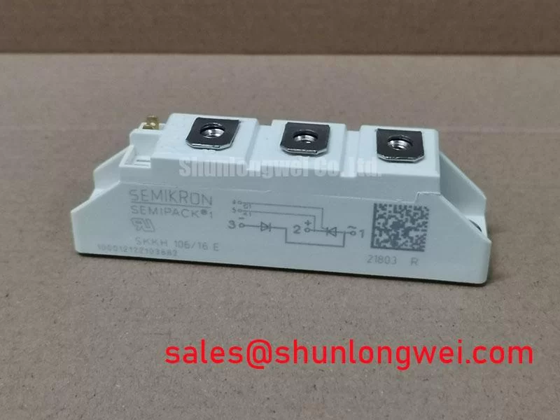
At a tripped high-current rectifier, isolate the DC bus, inspect the main terminals for heat discoloration, and compare cold-state terminal readings with a known-good phase before removing the module. The SKKH106-18E is a Semikron thyristor/diode module rated at 1800 V and 106 A, using the Semipack package format. These are official product specifications for initial replacement screening, not a complete system operating limit.
For a high-current green hydrogen electrolyzer DC power rectifier, confirm that the replacement matches the installed bridge topology, terminal arrangement, cooling interface, control timing, and protection network. The module’s voltage and current ratings provide the basic device identity, while actual operating suitability depends on the rectifier configuration, duty profile, commutation conditions, thermal path, fuse coordination, and enclosure design.
Control the current-rise event at the bridge terminals before investigating semiconductor damage. In a high-power rectifier, an unsuitable firing sequence, transformer leakage condition, or excessive wiring inductance can increase local current concentration during turn-on. The protection review should therefore begin with the installed RC snubber arrangement, the series saturable reactor if used, and the manufacturer’s fuse coordination data for the selected circuit.
Use the relevant Semikron fuse I2t coordination table when selecting or checking semiconductor protection. The fuse must be evaluated against the complete fault-clearing path, including prospective short-circuit current, line impedance, transformer characteristics, and the actual bridge arrangement. Do not substitute a fuse based only on its continuous current label. The coordination record should identify the approved fuse family, clearing behavior, and installation position used by the equipment designer.
For RC snubbers, inspect resistor condition, capacitor cracking, terminal security, and evidence of repeated pulse stress. The network is intended to limit transient voltage and suppress unwanted dv/dt triggering, but its values must be established from the circuit’s commutation behavior and the module’s applicable datasheet limits. A series saturable reactor can also moderate the initial current rise; its core condition, saturation behavior, and location in the power path require system-level verification.
The external Semikron reference for SEMIPACK thyristor and diode modules is useful when checking package conventions and application context. ⚠️ Field Alert: Follow the equipment drawing and the specified fastener procedure for terminal and heatsink installation, and apply thermal interface material evenly without contaminating the electrical contact surfaces.
SKKH106-18E Operational Boundaries: Evaluating Interphase Transformer Current Balancing Limits
In a six-pulse or twelve-pulse DC rectifier, current sharing must be checked across the complete transformer and bridge assembly rather than inferred from the module’s 106 A rating. A twelve-pulse arrangement normally uses phase-shifted secondary supplies and may use an interphase transformer to combine rectified outputs. The IPT magnetic design, winding resistance, leakage reactance, connection polarity, and saturation margin influence how evenly the parallel DC paths carry current.
During maintenance, verify that the bridge terminals are connected according to the original schematic and that no phase leg has been moved to a neighboring connection point. Inspect busbar joints for looseness, oxidation, or localized heating, then compare phase current measurements under controlled load conditions. Unequal current can result from transformer imbalance, wiring resistance, firing timing, sensor placement, or an abnormal semiconductor path, so the measurement set should include each relevant phase and DC combining point.
The SKKH106-18E can be evaluated as a replacement in a high-current electrolyzer rectifier when its electrical ratings, Semipack mechanical interface, and bridge topology match the installed design. A lower-rated related device such as SKKH91-18E should be treated as a separate selection requiring its own voltage, current, thermal, and protection review rather than assumed interchangeable.
Check the IPT and bridge assembly at energization, low-load operation, and the intended service load. The engineer responsible for the system should confirm current balance, transformer temperature, fuse coordination, and DC ripple against the equipment acceptance limits before returning the rectifier to continuous duty.
SKKH106-18E Operational Boundaries: Evaluating Commutation and Switching-Loss Dissipation Limits
When the rectifier operates with fast commutation or switching events, evaluate reverse-recovery behavior through the complete circuit rather than treating the module’s current rating as a switching-loss specification. Diode reverse-recovery peak current, recovery time, source impedance, transformer leakage, and stray bus inductance affect the turn-off transient and the resulting electromagnetic radiation.
Use oscilloscope measurements at the appropriate voltage and current sensing points to compare commutation behavior between phases. Probe placement must minimize pickup from the high-current loop, and the test setup must be rated for the DC-link environment. Look for excessive voltage overshoot, ringing, uneven recovery between bridge legs, or thermal rise that does not track the measured average current. These observations can indicate a mismatch between the snubber network, transformer behavior, layout, and operating frequency.
For a rectifier feeding a large electrolyzer DC load, keep the power loop compact and review laminated busbar geometry where practical. The design objective is to reduce parasitic inductance and control turn-off overshoot, while the final clearance, insulation, damping, and filtering decisions remain system-engineering responsibilities. Long conductors between the module, commutation path, and capacitor bank can increase ringing and should be assessed during switching tests.
The Semikron reference for CAL diode technology provides additional manufacturer context for diode technology, but it does not replace the electrical limits and test conditions applicable to this specific module. For broader rectifier and power-conversion integration guidance, review the Industrial Applications engineering resource.