Content last revised on October 4, 2026
SKKH91-18E Inspection and Application Overview
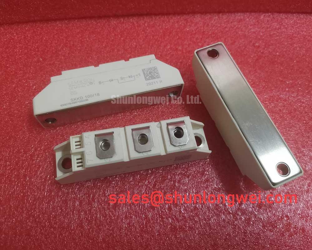
Before energizing a replacement, isolate the assembly, inspect the Semipack housing and terminals, and compare every terminal designation with the approved circuit drawing for SKKH91-18E. The documented device rating is 1800 V and 91 A, with a Semikron Semipack package. These are official product specifications supplied for this product page; they are not a substitute for the complete manufacturer datasheet, gate-drive limits, thermal curves, surge ratings, or fuse coordination data.
For incoming inspection, record the marking, check the housing for cracks or deformation, and verify that the power terminals and control terminals are clean and mechanically undamaged. With the module completely disconnected from the circuit, use the multimeter diode function to compare the documented thyristor conduction paths against a known-good reference. The measured result should be assessed by terminal identity and test polarity rather than by an assumed universal voltage value, because the internal circuit arrangement and test conditions determine the reading. A low-resistance reading in both directions, an open path where the approved reference conducts, or an unstable reading deserves isolation testing before installation.
The SKKH91-18E is a Semikron dual-thyristor module intended for evaluation in high-current power conversion equipment. Its potential application set includes grid-tied static Var compensators and thyristor-switched capacitor systems, subject to the voltage topology, firing circuit, cooling arrangement, protection network, and the complete system duty cycle. The product data available here confirms the voltage, current, and package class only. Designers should obtain the applicable Semikron mechanical drawing and electrical data before finalizing terminal wiring, gate-drive settings, mounting hardware, or protection components.
| Product | SKKH91-18E |
| Manufacturer | Semikron |
| Product category | Thyristor/Thyristor Module |
| Rated voltage | 1800 V Official Specification |
| Rated current | 91 A Official Specification |
| Package | Semipack Official Specification |
Transient Dynamics and Electrical Design for the SKKH91-18E
In a thyristor-switched capacitor branch, the first design task is to establish the actual voltage and current waveform at the module terminals during turn-on, commutation, and abnormal interruption. The 1800 V rating identifies the stated voltage class of the device, while the 91 A rating identifies the stated current class supplied for this listing. Those figures do not by themselves define repetitive surge capability, permissible rate of voltage rise, gate-trigger limits, thermal current, or short-circuit withstand. The system engineer should verify each missing limit from the relevant Semikron documentation before applying the part to an SVC topology.
RC damping is a design consideration when wiring inductance, capacitor-bank switching, or transformer leakage produces ringing across a thyristor junction. The resistor and capacitor values should be selected from measured overshoot, oscillation frequency, capacitor discharge energy, and the permitted loss of the actual switching network. A fixed RC network should not be copied from another module solely because its voltage and current labels appear similar. During bench work, place the measurement reference at the module power terminals and compare the waveform with the known-good switching path.
A series saturable reactor may be considered where the SVC topology produces a high initial current slope or capacitor inrush. Its selection is system-dependent and should be checked against the switching angle, capacitor-bank impedance, fault-clearing strategy, thermal duty, and the module’s documented surge limits. The purpose is to control transient current stress, not to compensate for an incorrectly timed gate pulse. Designers should also examine whether the reactor introduces a commutation condition that changes the voltage appearing across the inactive device.
Fuse coordination must be based on the manufacturer’s applicable I²t data, fuse class, prospective fault current, and clearing time. No fuse I²t value is supplied in the product information provided for this page, so a numerical coordination claim would be unsupported. The same applies to terminal torque and terminal spacing: use the mechanical drawing specified for the exact Semipack variant rather than borrowing values from a different package. The Semikron SEMIPACK® Thyristor / Diode Modules reference provides useful package-family context, while the exact product documentation remains the controlling source for installation.
For a field replacement review, compare the circuit function, voltage class, current class, package geometry, gate interface, and protection network before considering the related SKKH273/18E. It should be treated as a separate component for engineering verification, not as an automatic substitute.
SKKH91-18E Circuit Protection and Firing Delay-Angle Evaluation
Firing-angle adjustment in an AC controller changes the conduction interval and therefore changes the average power delivered to the connected network. In a grid-tied SVC or thyristor-switched capacitor assembly, the control engineer should evaluate the complete phase relationship among the line voltage, gate command, capacitor current, reactor current, and commutation event. The familiar firing-angle range from early conduction to late conduction is a system-analysis framework, not an additional factory specification for the SKKH91-18E.
When the firing delay is adjusted, monitor the line current and terminal voltage at the same time. A suitable test plan should identify whether the observed reactive-power change comes from the intended switching state or from incomplete commutation, gate timing asymmetry, supply distortion, or measurement-reference error. Power factor and harmonic current should be reviewed at the point of common coupling when the unit is evaluated in an SVC installation. The module itself cannot be described as independently compliant with an installation-level EMC or power-quality standard.
The gate circuit should be checked for correct polarity, pulse width, isolation, return path, and synchronization with the approved thyristor terminal definition. Do not infer gate pin assignments from package appearance. A cold resistance comparison can identify an obvious wiring mismatch, but it cannot confirm dynamic triggering. For that task, use an isolated oscilloscope arrangement and compare gate-to-reference and power-terminal waveforms under controlled voltage and current conditions.
Protection review should include semiconductor fuses, line reactors, snubbers, discharge paths, and the trip logic that removes gate commands during an abnormal condition. The values and ratings are determined by the SVC topology and must be verified against official device data. If the existing assembly has suffered a fault, inspect the gate transformer or optically isolated driver, capacitor-bank contactor logic, and current transformer polarity before installing a replacement. Replacing the power module without checking those surrounding circuits can leave the original stress mechanism unchanged.
For a practical incoming test, measure each documented conduction path in both meter polarities with the device isolated, then compare the result against an approved reference device at the same ambient condition. 💡 Bench Tip: Use ESD protection and record the cold-state reference before connecting any gate or power wiring.
Benchtop Waveform Tuning for Surge Energy and Clamping
AC input protection for a capacitor-switching branch should be evaluated as a coordinated network rather than as a single MOV placed near the semiconductor. A MOV selection is governed by the actual line-to-line or line-to-neutral exposure, continuous operating voltage, temporary overvoltage, surge energy, repetition rate, and the upstream protective device. The IEEE 61000-4-5 test environment can be used as a test reference where applicable, but a component should not be described as independently passing an equipment-level immunity test.
For the SKKH91-18E, the relevant bench observation is the voltage that reaches the module terminals during the switching edge and during the decay of stored energy. Use a properly rated differential probe and a current probe with an adequate bandwidth, and keep the measurement loop physically compact. The test fixture must reproduce the important source impedance, wiring inductance, capacitor-bank behavior, and grounding arrangement; otherwise, the recorded overshoot may not represent the installed equipment.
An RC snubber can reduce ringing when its impedance and energy rating are matched to the measured network. Its capacitor voltage rating, pulse capability, resistor pulse energy, discharge behavior, and temperature rise need verification. An MOV can clamp a surge but will not automatically remove repetitive switching oscillation. The protection stages should therefore be reviewed together with fuse clearing, contactor timing, reactor impedance, and the distance between the clamp network and the module.
During waveform tuning, begin with low-energy controlled tests and increase the operating condition only after the measured voltage and current remain within the approved device and fixture limits. Observe both polarities if the circuit is bidirectional. A trigger event that appears only on one half-cycle may point to gate synchronization, terminal-reference, wiring, or commutation behavior and should be investigated through waveform comparison rather than assigned to one cause without evidence.
The manufacturer’s technology references can help engineers understand the broader power-semiconductor context. Semikron’s CAL Diode Technology information is relevant to diode technology at the industry level, but it should not be used to infer unlisted internal construction or unprovided switching figures for this exact module. For gate-drive protection studies, the practical reference on Evolution of Negative Off-Bias Gate Drive Circuits may support a design review; the final gate strategy remains dependent on the approved circuit and device documentation.
Assembly Integrity and Layout Architecture for Commutation Control
Mechanical installation affects electrical repeatability because loose or uneven connections can add unwanted resistance, heating, and parasitic inductance. Before fitting the module, clean the mating surfaces according to the equipment maintenance procedure, verify the heatsink flatness, and confirm that the specified interface material is compatible with the Semipack assembly. The supplied product data does not include a mounting torque value, so the installer must use the exact Semikron mechanical drawing or equipment service document rather than applying an assumed torque.
Power conductors should be arranged to minimize the commutation loop area and to keep high-current paths away from sensitive gate wiring. This is a Design Consideration, not a guaranteed electrical parameter of the module. The final layout should be validated by measuring turn-off voltage, current transfer, ringing, and conducted noise under the actual switching condition. If a gate lead must cross a power conductor, follow the equipment’s isolation and routing rules and verify the resulting waveform at the device reference.
Thyristor turn-off and recovery characteristics are device and operating-condition parameters that must come from the applicable official data. They vary with junction temperature, forward current, rate of current change, circuit inductance, and test method. The product information available here does not specify tq, di/dt, dv/dt, or switching-loss values for SKKH91-18E. Engineers should therefore avoid calculating a commutation margin from assumed device figures and should instead validate peak voltage and current against the documented limits during controlled switching tests.
At the final inspection stage, confirm terminal identity against the approved drawing, check that control wiring cannot contact the power terminals, and retest the isolated conduction paths after mechanical tightening. Where a replacement is installed in a grid-tied static Var compensator, record the initial waveform, firing command, line current, and temperature reference so later troubleshooting has a traceable baseline. Any unexpected result should be compared with the known-good signal path and the original equipment documentation before further operation.