Content last revised on October 15, 2026
Field Diagnostics & Commissioning: Minimizing Commutation Turn-Off Voltage Spikes in SKKH250-16E Topologies
- Isolate the rectifier, discharge stored energy, and verify absence of voltage before disconnecting the SKKH250-16E power terminals.
- Compare the module terminal diagram with the equipment schematic, including thyristor gate and cathode connections.
- Inspect the heatsink contact surface, mounting hardware, and thermal interface for contamination, uneven seating, or deterioration.
- Check the firing circuit connections and insulation condition before reconnecting the gate leads.
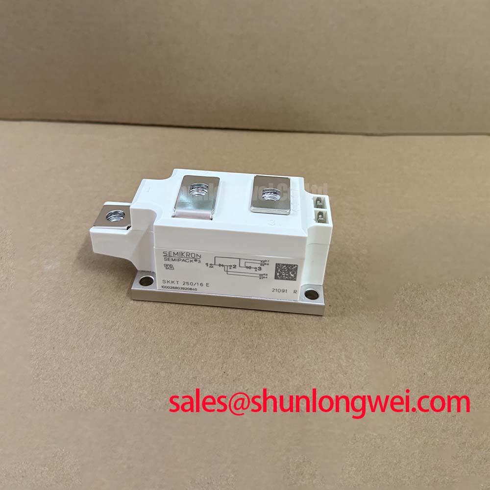
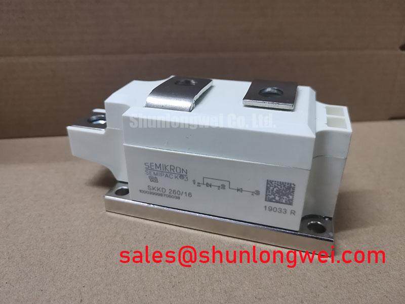
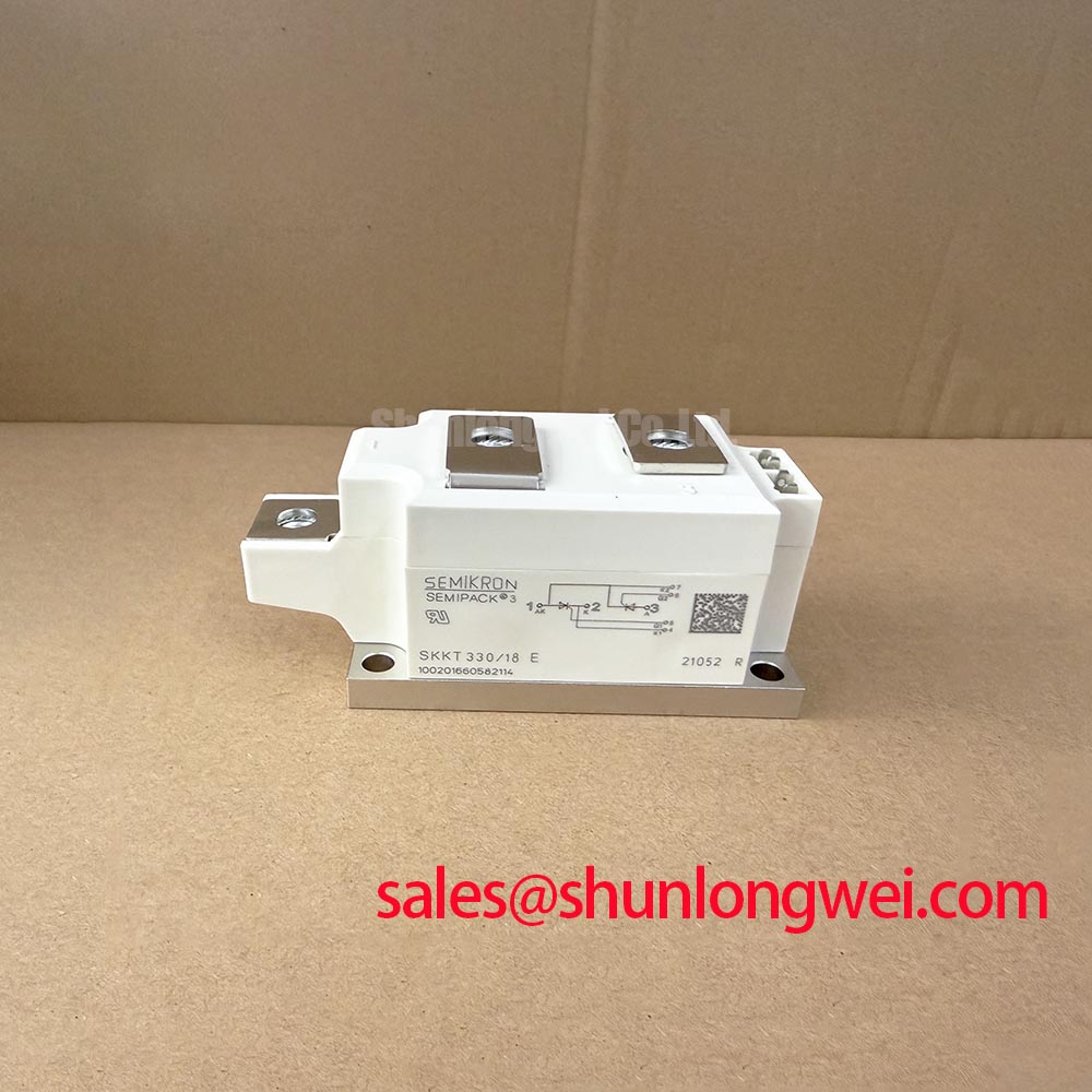
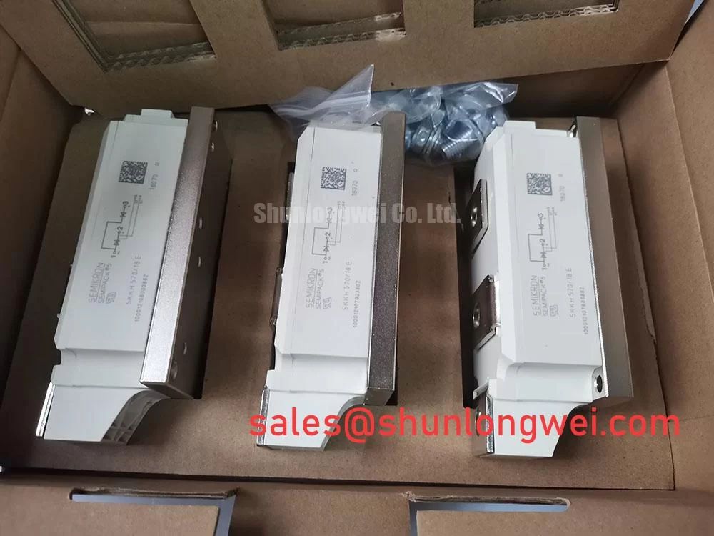
The Semikron SKKH250-16E is a thyristor/diode module in the SEMIPACK product family. Maintenance assessment should cover its electrical connections, firing circuit, cooling interface, and semiconductor fuse coordination together. A module change alone does not resolve a loose power connection or an interrupted cooling path.
| Product identification | Specification status |
|---|---|
| Model | SKKH250-16E |
| Manufacturer | Semikron |
| Product category | Thyristor/Diode Module |
| Package family | SEMIPACK |
| Blocking voltage, rated current, surge capability, gate limits, and tightening torque | Consult Datasheet for the exact module designation and applicable test conditions. |
Capture the voltage across the commutating device together with branch current when investigating repetitive voltage spikes. As a Design Consideration, the useful comparison is between operating conditions: firing angle, load current, supply condition, and module temperature should accompany each waveform record. Probe connections and measurement bandwidth also need attention because measurement-loop pickup can distort the apparent overshoot.
Diode reverse recovery peak current and recovery duration influence the current transferred during commutation. Recovery softness describes how that current decays; recovery time alone does not establish whether the resulting voltage transient will be acceptable. Compare recovery characteristics only under their stated current, temperature, and current-slope conditions. Evaluate any snubber or wiring adjustment through measurements on the actual assembly.
The Semikron SEMIPACK Thyristor / Diode Modules information provides manufacturer context for this module family. As an Engineering Recommendation, trace the commutation path through the bus connections, protection components, and transformer circuit before attributing an abnormal waveform to the semiconductor.
For compatibility assessment, a high-current green hydrogen electrolyzer DC power rectifier is one possible equipment context. Designers should evaluate bridge configuration, firing-angle range, cooling capacity, and protection coordination against the original assembly. Phase-angle control changes the input current waveform; harmonic mitigation belongs to the complete rectifier and supply design. A module replacement does not establish equipment EMC compliance.
Preventing Spurious Faults: Gate Trigger Current Dynamics Guidelines for SKKH250-16E
Measure gate current at the module connection when investigating missed firing or inconsistent conduction between branches. As a Design Consideration, compare the pulse front, amplitude, duration, and any subsequent pulse train with the thyristor trigger requirements and gate power limits. An acceptable driver output measured without its connected load does not establish correct triggering at the device.
Keep gate trigger current, latching current, and holding current distinct during diagnosis. The gate pulse initiates conduction; anode current must then establish and sustain the conducting state. A trailing gate pulse portion or repeated firing pulses should be assessed against the load-current build-up and permitted gate dissipation. These techniques should follow the equipment firing strategy rather than an assumed universal pulse prescription.
Inspect the gate return connection and routing relative to the power conductors. As an Engineering Recommendation, investigate common-mode disturbance and cathode-reference movement when trigger errors correlate with commutation events. Any negative gate bias requires evaluation against permissible gate voltage and the driver design; it should not be added as a routine maintenance adjustment.
When comparing the SKKH 162/16E, assess its circuit arrangement, current conditions, surge capability, gate requirements, and mechanical drawing independently. A related designation supports a comparison, but replacement approval depends on the complete electrical and mechanical match.
SKKH250-16E Thermal-Electrical Optimization: Non-Repetitive Surge On-State Current Practical Tuning
Match the non-repetitive surge-current rating to its specified waveform, initial junction temperature, and reverse-voltage conditions before reviewing fault protection. As a Design Consideration, a sinusoidal half-cycle test rating describes a defined event; it does not authorize repeated overload operation. Reverse-voltage reapplication must be assessed alongside the temperature reached during the surge.
Review semiconductor fuse coordination using the device and fuse documentation together. Compare total clearing I²t under the relevant circuit conditions, including the prospective fault current and recovery voltage. For repeated load pulses, transient thermal impedance provides the appropriate basis for evaluating junction-temperature excursions; steady-state thermal resistance alone does not describe a short pulse.
Maintenance Note: Monitor terminal temperature trends and inspect cooling airflow during scheduled maintenance so connection heating and obstructed heatsinks receive attention before recommissioning.
Set inspection intervals from contamination exposure, operating records, and equipment service instructions. Check thermal-interface condition when removing the module, and use the specified mounting and terminal tightening procedures during reassembly. After cold storage or temperature changes, assess condensation before energization. The Field Engineer’s Handbook supports broader troubleshooting practice, while the Semikron-Danfoss Power Modules Catalog provides manufacturer product context for checking the intended module family and assembly documentation.