Content last revised on September 20, 2026
Transient Dynamics & Electrical Design: Reverse Recovery Charge on SKKH 162/16E
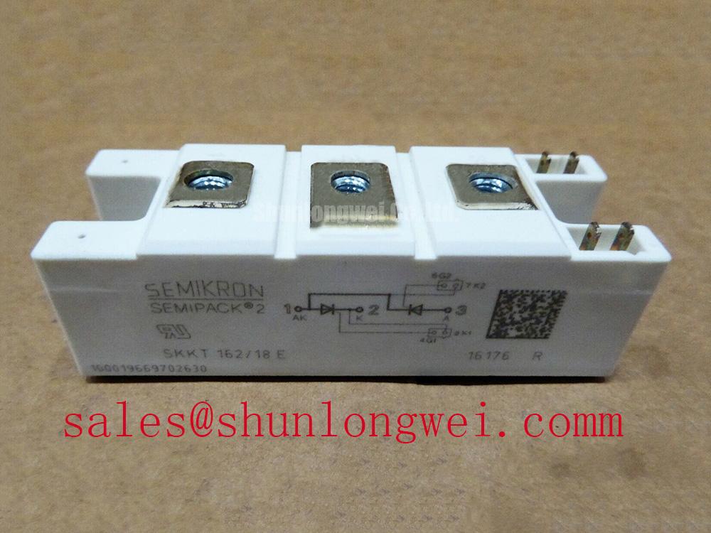
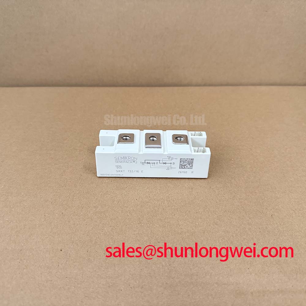
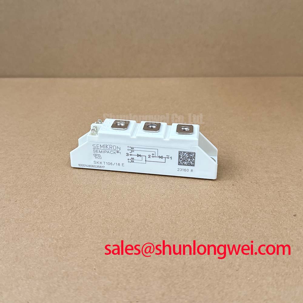
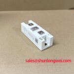
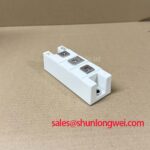
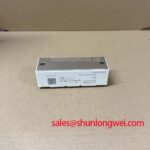
Verify the equipment bill of materials and the module nameplate before disconnecting the existing power assembly: SKKH 162/16E is identified in the supplied product data as a Semikron Semipack thyristor/diode module rated at 1600 V and 162 A. These are Official Specification values provided for this product page and should be matched against the controlled documentation of the installed converter before any replacement decision or commissioning work.
The Semipack housing is intended for power assemblies where electrical terminals, the heat spreading path, fuse coordination, trigger circuitry, and mechanical clamping must be assessed as one serviceable unit. In a medium frequency induction melting or metal hardening power supply, a module is only one part of a commutation and thermal system. Maintenance personnel should therefore record the existing terminal routing, heatsink condition, gate trigger wiring, protective network arrangement, and fuse markings before removing the module.
| Product identifier | Official Specification |
|---|---|
| Model | SKKH 162/16E |
| Manufacturer | Semikron |
| Module category | Thyristor/Diode Module |
| Voltage rating | 1600 V |
| Current rating | 162 A |
| Housing | Semipack |
In a line commutated or resonant induction heating power stage, current transfer between the thyristor path, associated diode path, transformer leakage inductance, and output network determines whether the module experiences a controlled commutation event or an excessive transient. The supplied specification confirms the module voltage and current identity, but it does not provide reverse recovery charge, reverse recovery peak current, reverse recovery time, gate trigger current, gate trigger voltage, surge current, or fuse I²t data. Those values must be taken from the controlled Semikron datasheet applicable to the exact suffix and production documentation, rather than inferred from the Semipack family name.
Reverse recovery is particularly relevant where a diode transitions from forward conduction into blocking while current is being redirected elsewhere in the circuit. Recovery current can interact with commutation inductance and create voltage stress at the module terminals. A waveform that appears acceptable at a controller test point can differ materially from the waveform across the power module because terminal layout and measurement probe grounding influence the observed result. During fault investigation, measure at the relevant power terminals with a suitably rated differential measurement method and compare the timing with the known gate command and AC source reference.
Design Consideration: keep the commutation path compact and use the original busbar geometry where possible, because loop inductance contributes to switching overshoot during rapid current change. The system engineer should verify peak terminal voltage against the 1600 V official voltage rating during representative switching tests, including the expected operating temperature and load condition. Do not convert a general rule about low inductance into a fixed layout target without evaluating the complete converter assembly.
Fuse selection must be checked against the system’s published semiconductor fuse coordination data. Fuse I²t, prospective fault current, cable impedance, transformer behavior, and the fault clearing path are system dependent. No I²t figure is stated in the supplied SKKH 162/16E data, so a replacement module should not be approved by assuming that the fuse used with a differently rated Semipack assembly remains suitable.
For component family context, Semikron identifies the SEMIPACK® thyristor and diode module range as a power module product line. That family reference is useful for understanding the housing category, but the exact terminal configuration and dynamic characteristics must always be confirmed for SKKH 162/16E itself.
Benchtop Waveform Tuning: Mitigating Stress via AC Input Transient Overvoltage Clamping on SKKH 162/16E
Before applying mains power after a module change, inspect the AC input protective chain as a connected circuit rather than treating the replacement module as the only service item. Check the condition of surge protection devices, snubber capacitors, resistor bodies, connection lugs, fuse clips, contactors, and suppression wiring. Heat discoloration, loose hardware, cracked encapsulation, or a change in the original routing can indicate that the source of a transient event lies outside the power module.
Metal oxide varistors and RC snubber stages are commonly used at appropriate points in industrial converter assemblies to limit transient energy and control rapid voltage transitions. Design Consideration: their choice depends on the actual AC supply, the upstream protective device, expected surge exposure, circuit topology, capacitor voltage capability, resistor pulse capability, and the measured terminal waveform. The system integrator should select or validate these networks against the machine documentation and bench measurements. A generic MOV part number or RC value cannot be prescribed from the SKKH 162/16E voltage and current ratings alone.
Surge immunity testing is often discussed with reference to IEC 61000-4-5 at equipment level. A power semiconductor module cannot by itself be represented as certified to an installed machine’s surge or EMC requirement. The final result depends on enclosure bonding, cable entry, filter arrangement, grounding architecture, source impedance, and the coordinated behavior of the entire power supply.
When a previously stable induction furnace begins opening protective devices during startup, compare the AC input waveform and firing command sequence with a documented healthy machine if one is available. Check whether an input transient occurs before gating, during phase transfer, or under load. This approach avoids assigning the cause to diode recovery, a snubber, or a gate board before evidence supports that conclusion.
The related SKKD162/12 should be treated as a separate reference model for documentation comparison, not as an automatic replacement determination. Differences in voltage rating, internal configuration, terminal assignment, control requirements, and the host circuit can change whether a module can be considered during a controlled engineering review.
Field Diagnostics & Commissioning: Mechanical Mounting Torque Sequence and Thermal Path in SKKH 162/16E Topologies
With the converter isolated, discharged, and locked out under the site procedure, inspect the heatsink contact area before fitting the SKKH 162/16E. Remove old thermal interface residue without scratching the mounting surface, then examine the heatsink for raised burrs, corrosion, local distortion, or embedded debris. A clean, flat contact zone allows the module base and heatsink to form a predictable thermal path; uneven contact can create local thermal stress even if electrical commissioning initially appears normal.
The supplied information identifies the enclosure as Semipack, but it does not state a module specific mounting torque, mounting screw size, thermal resistance from junction to case, thermal resistance from case to heatsink, or thermal interface thickness. These values must be verified from the applicable official module documentation and the equipment manufacturer’s mechanical drawing. Do not apply a torque figure obtained from another module or a general fastener table as if it were an official SKKH 162/16E specification.
Install fasteners in a controlled cross pattern and increase clamping progressively to maintain even contact pressure. Terminal hardware should be tightened according to the module documentation and equipment assembly procedure, with conductor orientation arranged so that cable strain does not load the terminal during thermal cycling. After installation, verify that no busbar edge, washer, or lug contacts an unintended surface and that clearances match the original assembly.
⚠️ Maintenance Note: Periodically monitor terminal temperature rise, inspect aging thermal interface material, and confirm that cooling passages remain clear before a seasonal increase in furnace duty.
Commissioning checks should begin at the lowest permitted system energy condition and should include verification of the intended gate command sequence, terminal voltage behavior, cooling airflow or coolant flow indication, and protective interlocks. A localized temperature difference may indicate uneven mounting contact, degraded thermal material, reduced cooling performance, unequal current sharing in a parallel circuit, or an external connection issue. It should be investigated through measurements and inspection rather than treated as proof of one specific failure mechanism.
For long term maintenance planning, condensation control and contamination management matter as much as the initial installation. Keep conductive dust away from terminals and gate connections, inspect cooling hardware at scheduled shutdowns, and investigate water ingress or condensation before returning high current equipment to service. The module’s published electrical ratings do not establish suitability for a particular humidity, altitude, insulation coordination, or enclosure condition.
Benchtop Waveform Tuning: Mitigating Stress via Dynamic Firing Delay Angle Adjustment on SKKH 162/16E
Firing delay angle determines when a controlled rectifier or phase controlled power circuit begins conduction within the available AC cycle. In induction melting and hardening equipment, adjustments to this timing affect the resulting DC link behavior, transformer loading, reactive power demand, and current waveform. The appropriate firing range is set by the complete converter topology, line frequency, source impedance, control strategy, load condition, and protection logic. It cannot be derived solely from the 1600 V and 162 A official SKKH 162/16E ratings.
During controlled bench validation, record the synchronized AC reference, gate pulse timing, module terminal waveform, DC output response, and protective signals together. This makes it possible to determine whether unexpected current asymmetry follows a timing issue, a missing or degraded trigger pulse, an AC supply imbalance, a commutation network condition, or a downstream load change. Verify pulse delivery at the module connection under the relevant operating condition, rather than relying only on a logic level observed at the controller output.
Design Consideration: a gate drive arrangement should provide repeatable triggering under the operating conditions defined by the equipment manufacturer. The required gate trigger characteristics are not included in the supplied SKKH 162/16E data, so gate pulse amplitude, duration, repetition, isolation method, and firing delay limits require confirmation from the official datasheet and original control documentation. Do not apply IGBT desaturation protection, soft turn off behavior, short circuit safe operating area assumptions, or negative gate bias practices to this thyristor/diode module category, because those functions belong to different device technologies and control methods.
Where the existing induction power source uses parallel current paths, static and dynamic current sharing should be assessed from measured current and timing data. Device temperature, conductor symmetry, trigger timing, and external impedances can all affect the result. The technician should preserve matched routing and verify the system response after each controlled change, especially when replacing a module within an older assembly.
For engineers evaluating newer power semiconductor approaches in a separate system design exercise, the Wide Bandgap Revolution technical guide outlines design considerations associated with GaN and SiC devices. Such technologies should be evaluated at system level; they do not establish a direct substitution path for the SKKH 162/16E.