Content last revised on October 14, 2026
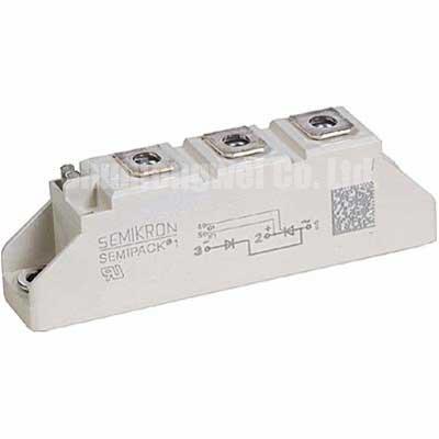
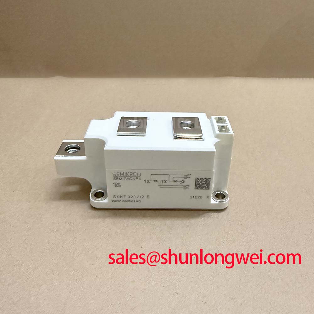
SKKD162-14 Semikron 1400 V 162 A Diode Module
When a high current rectifier reports an unstable DC output, isolate the power stage, inspect the terminal connections, and compare the installed device with the equipment bill of materials before applying reverse voltage again. The SKKD162-14 is a Semikron Semipack diode module with an official rated voltage of 1400 V and an official rated current of 162 A.
These figures identify the device for replacement screening in high-current rectifier assemblies. They do not, by themselves, define the complete operating envelope of a finished converter. The heat sink, cooling path, commutation arrangement, fuse coordination, terminal hardware, ambient conditions, and electrical duty must be reviewed as one system.
- Manufacturer: Semikron
- Part number: SKKD162-14
- Product category: Diode Module
- Package: Semipack
- Rated voltage: 1400 V, Official Specification
- Rated current: 162 A, Official Specification
Preventing Spurious Faults: Evaluating Post-Surge Reverse-Voltage Guidelines for SKKD162-14
After a surge event, keep the rectifier isolated until the current path, fuse condition, and thermal interface have been checked. The relevant field question is whether the module can be returned to reverse-voltage duty within the limits of the original power-stage design. A sinusoidal half-cycle surge can leave heat concentrated at the junction, so the engineering team should review the manufacturer’s surge-current and junction-temperature data before reapplying voltage.
Fuse coordination should be made against the applicable device I²t data rather than against the nominal current rating alone. Check the fuse manufacturer’s clearing characteristic, prospective fault current, cable impedance, and the semiconductor protection table used by the converter builder. If the original fuse arrangement is unavailable, treat the replacement as a system protection review rather than a direct component substitution.
Terminal pressure and heat-sink contact are equally important during reassembly. Clean the mating surfaces, preserve the intended washer and busbar arrangement, and apply the equipment manufacturer’s specified tightening procedure. Safety interlock note: disconnect and verify the DC link is discharged before touching terminals or removing the module.
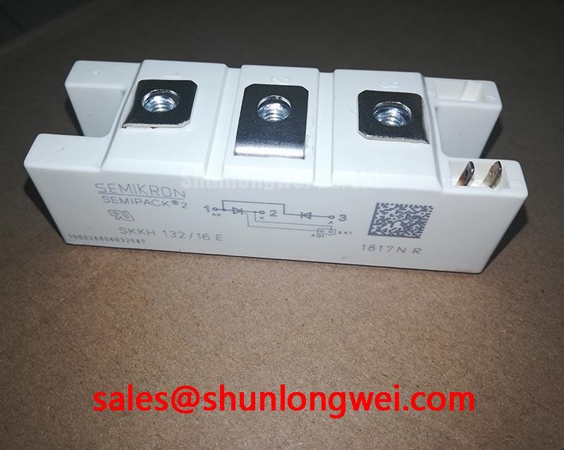
For a controlled replacement review, engineers may also compare the circuit position with the SKKH 162/16E as a separately specified Semikron sourcing reference. Electrical interchangeability still depends on the original bridge topology, voltage class, current duty, mounting arrangement, and protection network.
Transient Dynamics & Electrical Design: 6-Pulse and 12-Pulse Bridge Configurations on SKKD162-14
In a six-pulse bridge, confirm the device position, phase sequence, commutation path, and DC output polarity before energizing the transformer secondary. A twelve-pulse arrangement adds a phase-shifting transformer structure and normally requires careful current sharing between bridge groups. Where an interphase transformer is used, inspect its winding connections, polarity, saturation condition, and mechanical integrity before attributing unequal current to the semiconductor module.
The 162 A official current rating is a component identification parameter, not a complete guarantee of the available DC output in every bridge. Designers should verify conduction angle, cooling performance, transformer impedance, parallel path balance, and the actual rectifier duty. In a green hydrogen electrolyzer DC power rectifier, these checks are particularly relevant because a small imbalance between bridge paths can increase local heating and alter fuse stress.
Use symmetrical busbar routing where the topology permits it, and keep high-current connections mechanically secure. The external Semikron reference for SEMIPACK® Thyristor and Diode Modules provides useful product-family context for mechanical and electrical integration. It should not be treated as a substitute for the exact device documentation used in the equipment design.
Field Diagnostics & Commissioning: Reverse-Voltage Transients in SKKD162-14 Topologies
Commissioning should focus on the voltage transition seen by the reverse-biased device and on whether the snubber network matches the commutation behavior of the complete bridge. An RC snubber is selected from measured switching conditions, device data, stray inductance, and acceptable loss. The resistor and capacitor must be rated for the repetitive pulse energy and insulation environment established by the converter designer.
Where a series saturable reactor is part of the rectifier, inspect its core condition, winding connections, and installation position. It can influence the initial current rise and help distribute commutation stress, but its suitability is determined by the transformer, load profile, control sequence, and fault behavior. Avoid changing the snubber or reactor by trial substitution without recording the voltage waveform at the device terminals.
For troubleshooting, compare a suspected branch with a known-good phase using appropriately rated differential measurement equipment. Look for unequal reverse voltage, abnormal commutation overlap, localized heating, or recurring fuse operation, then correlate those observations with terminal torque, thermal contact, bridge polarity, and protection timing. The application article Unlocking Efficiency in Industrial Drives can serve as a broader switching-system reference when reviewing transient margins, although the SKKD162-14 remains a diode module and must be evaluated using its own device data.