Content last revised on October 12, 2026
Assembly Integrity & Layout Architecture: Reverse-Recovery Behavior for SKKH162-14E
- Isolate the converter and verify cold terminal condition before any resistance or continuity check.
- Confirm the replacement footprint, baseplate seating, heatsink flatness, and terminal alignment.
- Inspect the gate and control wiring for insulation damage, loose hardware, and contamination.
- Record the original phase arrangement and fuse coordination before removing the installed module.
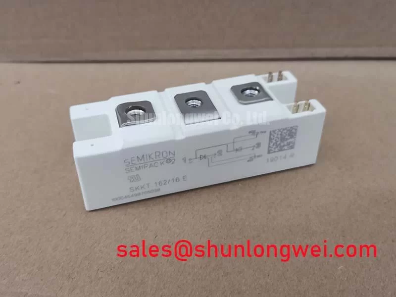
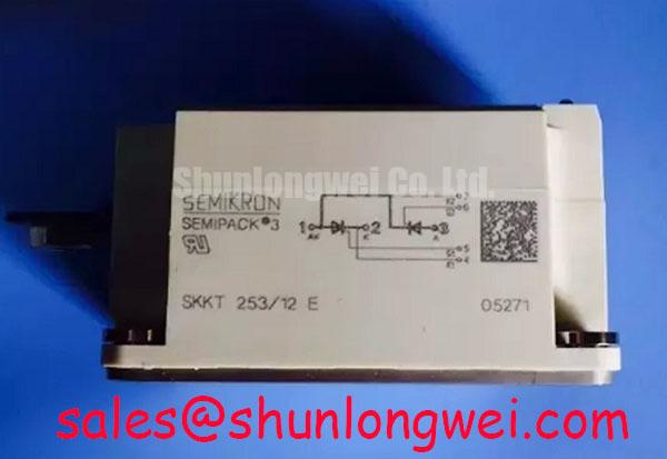
SKKH162-14E is a Semikron Semipack thyristor/diode module listed with an official voltage rating of 1400 V and an official current rating of 162 A. These values identify the catalog configuration; the actual operating point remains dependent on the circuit topology, cooling arrangement, switching duty, protection scheme, and installation conditions.
| Manufacturer | Semikron |
| Part number | SKKH162-14E |
| Product category | Thyristor/Diode Module |
| Package | Semipack |
| Voltage rating | 1400 V, Official Specification |
| Current rating | 162 A, Official Specification |
For a grid-tied static Var compensator or thyristor-switched capacitor stage, the module should be evaluated against the complete commutation network rather than by nameplate current alone. Phase-angle control, capacitor bank impedance, line inductance, fuse behavior, and the selected firing circuit all affect electrical stress and harmonic performance. The Semikron SEMIPACK® Thyristor / Diode Modules product information provides useful package-family context for mechanical and electrical integration.
Reverse-recovery behavior must be assessed at the installed circuit operating point, with attention to reverse-recovery peak current, recovery time, junction temperature, and the commutation path. These values influence switching loss and can increase conducted or radiated disturbance when the layout contains unnecessary stray inductance. Use the applicable manufacturer data for the selected operating conditions rather than transferring values from another Semipack device.
During assembly, keep the high-current path short and symmetrical where the topology permits. Busbar contact surfaces should be clean, flat, and free from burrs. Terminal hardware must be tightened according to the applicable Semikron mechanical instruction, with a calibrated tool and a documented sequence. The fuse I²t coordination table should be checked against the protection device and the prospective fault current of the installation; this is a system coordination task, not a substitute for the module rating.
The SKKH106-14E can serve as a neutral same-family reference during a footprint or electrical comparison, but its ratings and thermal behavior should not be transferred to SKKH162-14E. For the installed unit, verify terminal polarity, gate wiring, and the firing circuit’s return path before energization.
Benchtop Waveform Tuning: Evaluating Post-Surge Reverse-Voltage Blocking on SKKH162-14E
Surge evaluation should begin with the sinusoidal half-cycle duty expected from the SVC or thyristor-switched capacitor assembly. The relevant datasheet surge-current and duration limits must be matched to the actual line event, fuse clearing behavior, repetition rate, and junction temperature. Do not treat a single successful surge capture as proof of continuous operating margin.
Use an isolated, properly rated measurement arrangement to observe the current transition and the reverse voltage applied after conduction ends. The waveform should be reviewed for excessive overshoot, abnormal ringing, uneven phase behavior, and delayed recovery. If reverse voltage returns before the device has completed its recovery process, the commutation network may impose additional stress. Designers should therefore verify the post-surge waveform against the original protection and firing design before returning the unit to service.
In capacitor-switching equipment, phase-angle control also affects the amount of current drawn from the grid and the resulting harmonic spectrum. Filter tuning, switching timing, and system impedance belong to the SVC design authority. The module provides the controlled semiconductor switching function, but it does not independently establish compliance with grid-power-quality or EMC requirements. The SKKT-106B16E may be reviewed as a related front-end rectifier reference where the wider topology includes a separate rectification stage.
Preventing Spurious Faults: Baseplate Thermal Resistance Guidelines for SKKH162-14E
Thermal verification should focus on the complete heat path from the semiconductor junction through the copper baseplate, interface compound, heatsink, and airflow path. Uneven contact pressure can create localized thermal resistance even when the heatsink appears clean. Before installation, inspect the mounting surface for contamination, warpage, and trapped particles; apply the approved thermal interface material as a thin, even layer without allowing it to enter electrical terminals.
Use the manufacturer’s mounting sequence and torque specification for the Semipack package. Tightening one fastener fully before the others can distort the baseplate or reduce contact uniformity. After commissioning, compare phase temperatures under matched load conditions and inspect the air path for dust accumulation, blocked filters, and recirculated hot air.
Maintenance Note: Schedule periodic heatsink cleaning and monitor contact temperature trends so gradual airflow restriction or interface-material ageing is identified before nuisance trips occur.
For equipment installed at high altitude or in environments subject to condensation, the enclosure design should be reviewed for cooling performance, insulation spacing, moisture control, and transient exposure. Any assessment involving cosmic-ray effects, single-event burnout, FIT data, or altitude derating requires authoritative device and system reliability data; those topics should not be inferred from the package name or nominal current. Practical integration guidance for gate control, thermal management, and power circuit layout is available in IGBT Design & Integration.