



Content last revised on September 15, 2026
Field Diagnostics and Commissioning: Mechanical Mounting Torque Sequence and Thermal Contact
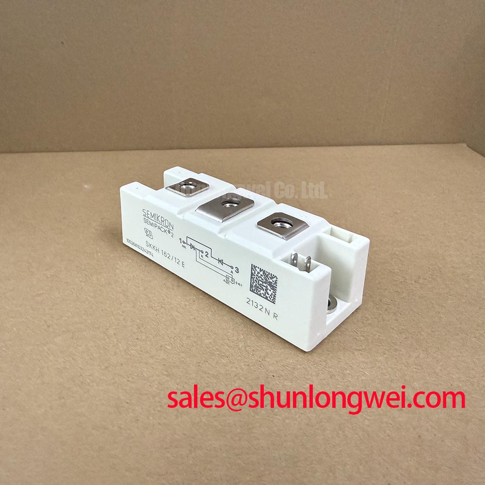
The factory-rated IT(AV) is 156 A at Tcase = 85 °C, while the continuous RMS on-state current rating is ITRMS = 250 A. These figures describe semiconductor current capability under their specified conditions; they do not replace a complete thermal calculation for the heatsink, airflow, duty cycle, or enclosure. The specified junction-to-case thermal resistance is Rth(j-c) = 0.18 °C/W per semiconductor chip, so thermal interface quality must be checked as part of commissioning rather than treated as a mechanical detail.
| Parameter | Official factory specification |
|---|---|
| Repetitive peak reverse voltage | VRRM = 1200 V |
| Average on-state current | IT(AV) = 156 A at Tcase = 85 °C |
| RMS on-state current | ITRMS = 250 A |
| Surge on-state current | ITSM = 5000 A at Tj = 125 °C, 10 ms half-sine |
| I²t withstand value | 125,000 A²s at Tj = 125 °C, 10 ms |
| Critical voltage rise rate | dv/dtcr = 1000 V/µs |
| Operating junction temperature | −40 °C to +125 °C |
| Isolation voltage | Visol = 3000 V AC for 1 minute |
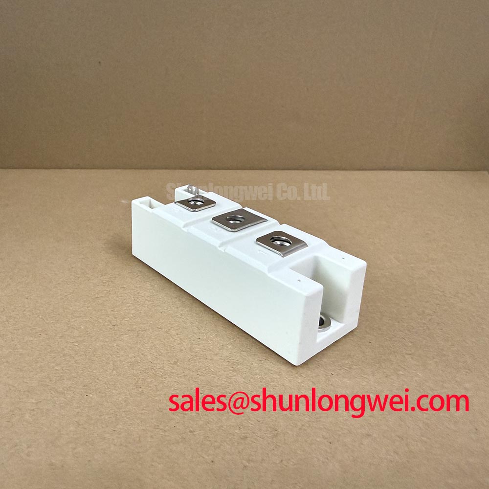
| Package | SEMIPACK 2, 94 × 34 × 30 mm |
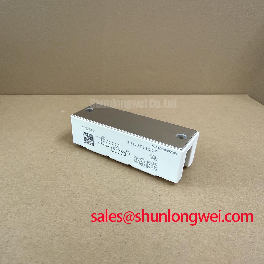
Use the heatsink manufacturer’s approved mounting procedure and tighten the fixing hardware in a balanced sequence so the baseplate seats evenly. Mounting torque is a Design Consideration governed by the module documentation, fastener size, heatsink material, and interface hardware; the supplied factory data does not define a universal torque value. After mounting, inspect the thermal compound spread at the accessible interface and verify that the module has not bowed against the heatsink.
Bench Diagnostic: Do not insert or remove power terminals while the DC link or AC supply is energized, even when the control circuit appears inactive.
Terminal identification, conductor cross-section, busbar clearance, and connection torque should be taken from the applicable Semikron mechanical drawing and the original soft-starter assembly record. A cold resistance check can identify an open connection or an unexpected short, but it cannot validate blocking performance at rated voltage. Insulation testing must also follow the applicable test method for the finished equipment. The module’s stated 3000 V AC one-minute isolation rating applies to the specified insulation path, such as between the electrically isolated terminals and baseplate, and is not a blanket field-test setting.
Assembly Integrity and Layout Architecture: Type-2 Coordination for Dead-Short Protection
The SKKH162/12E provides an official I²t value of 125,000 A²s under the stated 10 ms condition at Tj = 125 °C. This value is a semiconductor withstand reference, not a complete fuse-selection instruction. In a soft starter, the semiconductor fuse, line impedance, busbar arrangement, fault-clearing time, and prospective short-circuit current must be evaluated together.
For Type-2 coordination, the engineering task is to compare the selected semiconductor fuse clearing energy with the thyristor/diode module’s applicable I²t withstand data. The fuse manufacturer’s time-current and let-through tables are required for that comparison. A fuse can interrupt a fault while still allowing damaging peak current, arc energy, or mechanical stress elsewhere in the assembly, so the completed panel requires verification of conductor bracing, terminal security, enclosure containment, and post-test insulation condition.
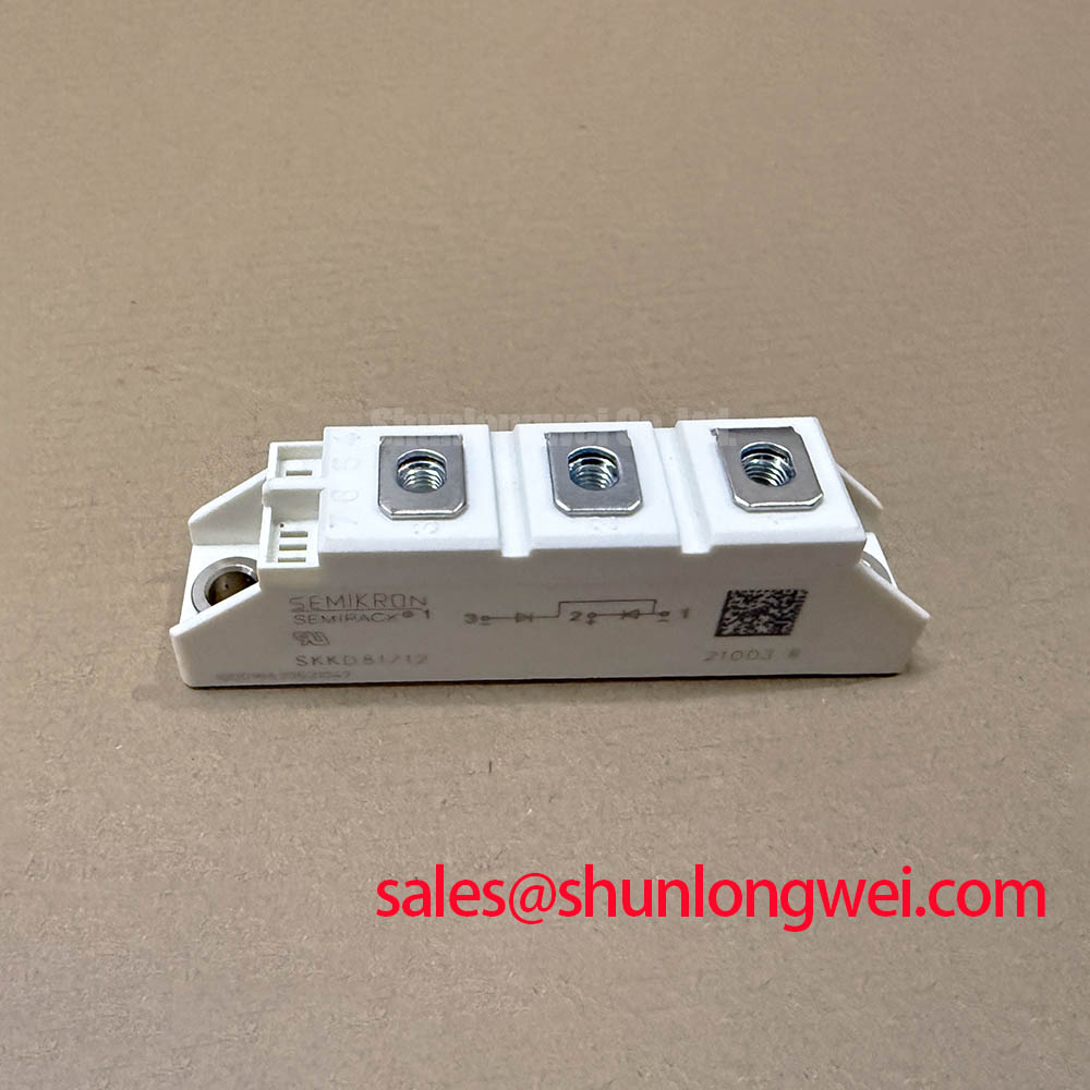
The 5000 A ITSM rating applies to the specified half-sine surge condition and should not be interpreted as permission for repeated dead-short exposure. Designers should coordinate the protection device with the actual phase topology and fault loop, then validate the result through the equipment’s approved short-circuit test method. The neutral reference model [SKKD162/12](https://www.slw-ele.com/skkd162-12.html) may be reviewed as a related Semikron product, but electrical substitution requires direct comparison of circuit configuration, ratings, dimensions, and control requirements.
Transient Dynamics and Electrical Design: Gate Trigger Current Behavior
Gate triggering in a thyristor soft starter depends on the gate-cathode circuit, pulse transformer or driver arrangement, wiring inductance, pulse amplitude, pulse duration, synchronization, and the load’s instantaneous voltage and current conditions. The supplied official parameter set for this product does not specify gate trigger current, gate trigger voltage, gate pulse rise time, holding current, latching current, or a required multi-pulse sequence. Those values must therefore be verified from the applicable Semikron electrical datasheet before designing the firing circuit.
A Design Consideration is to keep the gate return path controlled and physically close to its associated power-device terminals. Minimize parasitic loop inductance to reduce false triggering and pulse distortion, particularly where the soft starter shares a crowded busbar with high di/dt current paths. The system engineer should check gate-to-cathode waveforms with an isolated measurement arrangement and confirm reliable triggering across the intended temperature, line angle, and load-current range.
Active clamping, Miller-platform terminology, and negative gate bias practices are not automatically applicable to this thyristor/diode module. Any gate-bias or suppression method should follow the applicable thyristor gate-circuit documentation. For this device, the practical protection focus is controlled trigger timing, immunity to excessive dv/dt, and avoidance of unintended turn-on. The official dv/dtcr rating is 1000 V/µs; the finished circuit must be tested against actual commutation transients rather than assumed from a nominal schematic.
Where the module is used alongside an upstream controlled rectifier or related conversion stage, engineers can examine the topology relationship with [SKKT273/12E](https://www.slw-ele.com/skkt273-12e.html). This is a neutral reference to a related product and is not a substitute recommendation.
Field Diagnostics and Commissioning: Reverse Recovery Charge in Thyristor and Diode Topologies
Reverse recovery behavior influences commutation stress, switching loss, acoustic noise, and conducted or radiated interference in a three-phase soft starter. However, the supplied factory parameters do not state diode reverse-recovery charge, peak reverse-recovery current, recovery time, or a soft-recovery factor for the SKKH162/12E. These characteristics should be obtained from the correct manufacturer test documentation or measured on an appropriately controlled test bench.
During commissioning, observe phase voltage, device current, and the gate trigger waveform together. Look for abnormal commutation overshoot, ringing, uneven phase behavior, or a trigger pulse that changes shape when the motor is connected. Such observations may indicate layout coupling, snubber interaction, transformer leakage, load asymmetry, or an unsuitable measurement reference; they do not establish a single fault cause without comparison against a known-good signal path.
The module’s 1200 V repetitive peak reverse voltage rating provides the stated blocking boundary, while the actual peak voltage in the equipment depends on the power topology and transient-control network. Designers should minimize high-current commutation loop area, evaluate snubber placement at the circuit level, and verify peak margins during switching tests. The [Wide Bandgap Revolution](https://www.slw-ele.com/topic/wide-bandgap-revolution-core-advantages-and-design-challenges-of-gan-and-sic-power-semiconductors) article offers broader context on fast-switching semiconductor layout and transient behavior, although its principles should be applied here only where relevant to the actual circuit.
For product-line context, consult the Semikron SEMIPACK® Thyristor / Diode Modules reference and confirm the exact electrical, mechanical, and thermal documentation before releasing a replacement into service.