



Content last revised on October 1, 2026
SKKD162-18 Thermal-Electrical Optimization: Dynamic Firing Delay Angle Adjustment Under Practical Tuning
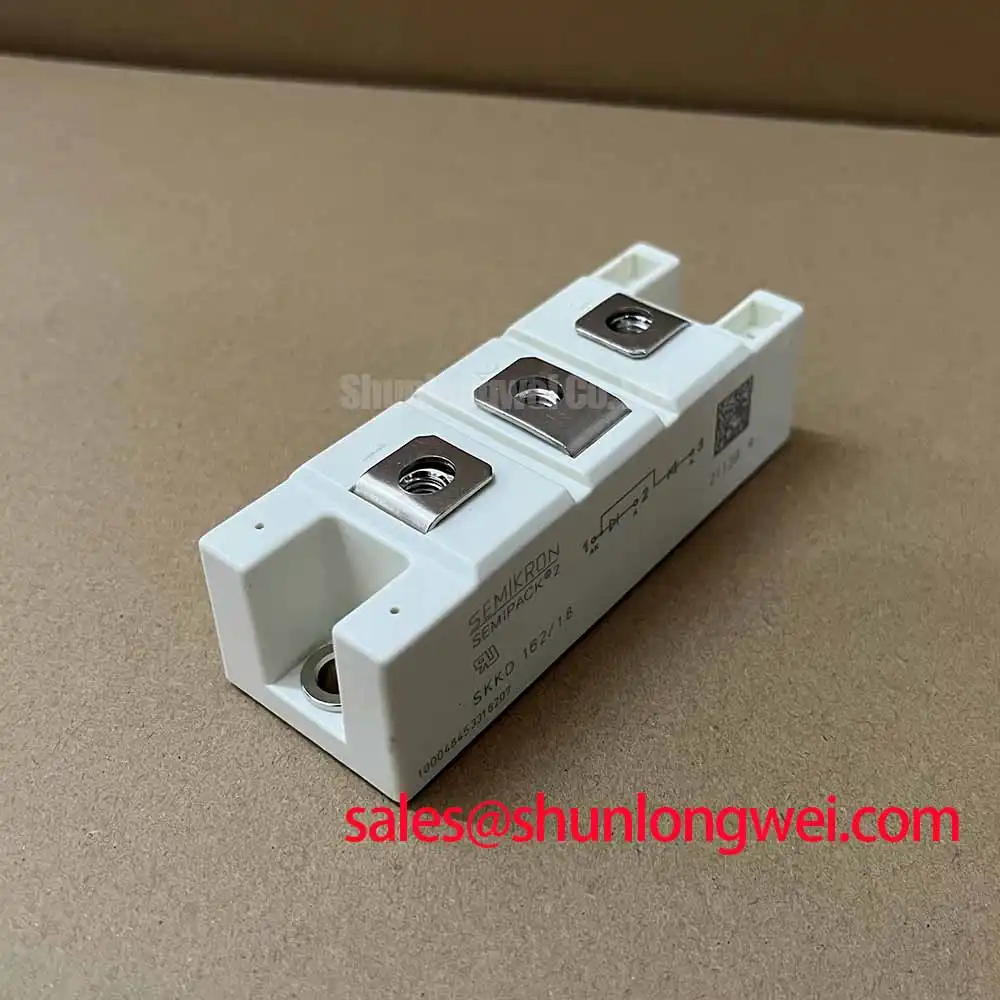
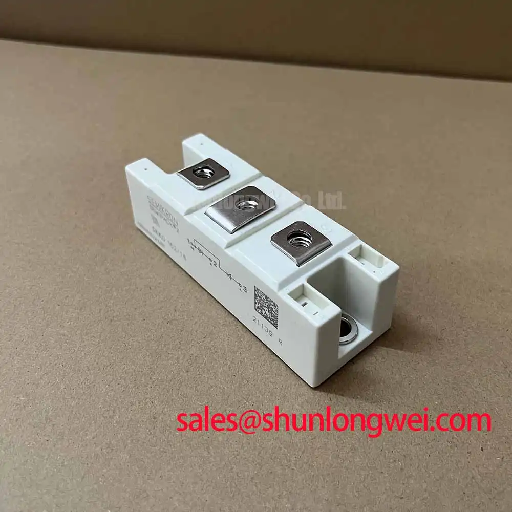
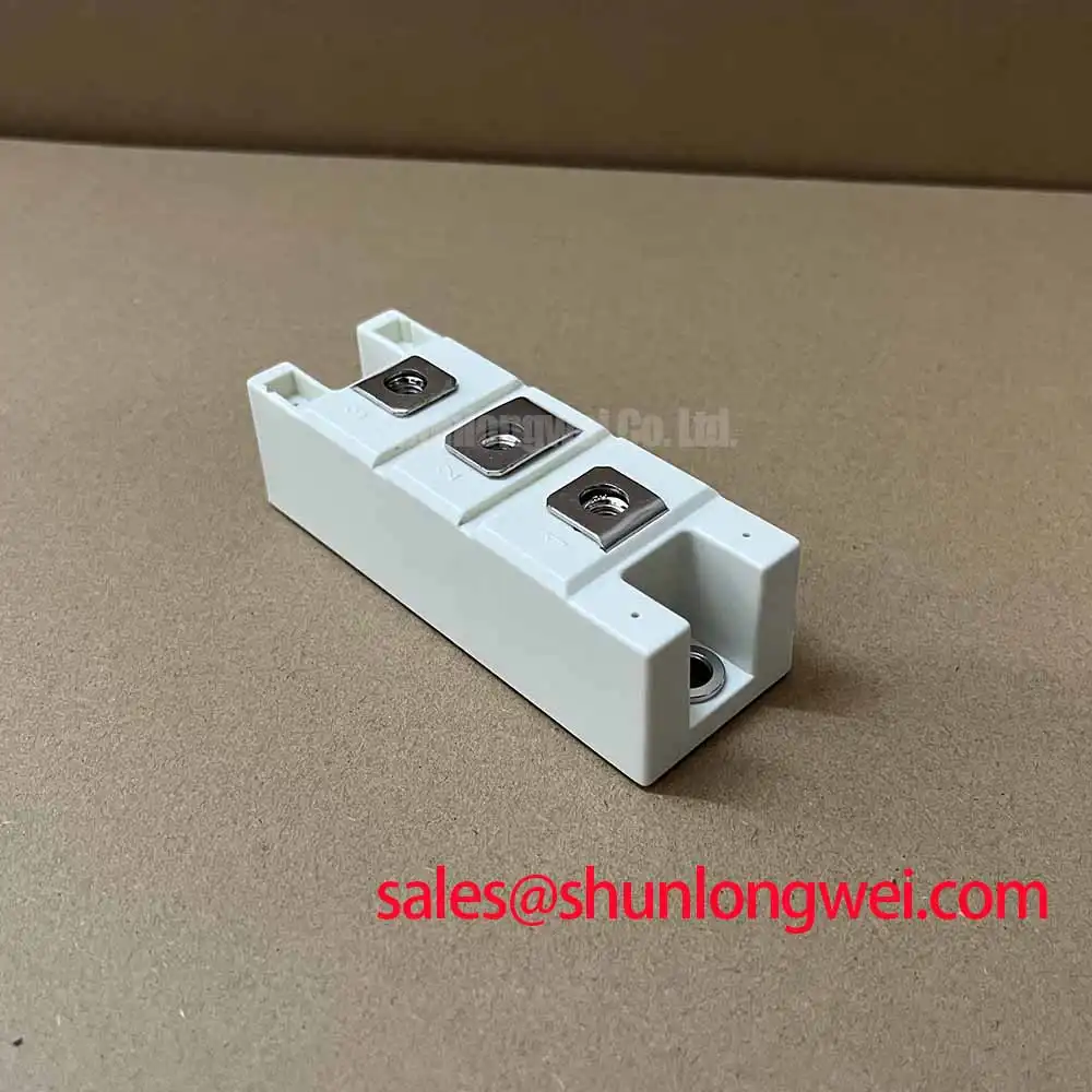
Measure the gate and main terminal wiring for continuity, loose hardware, and abnormal cold-state impedance before applying a firing signal to the rectifier assembly. The SKKD162-18 is a Semikron Semipack thyristor/diode module with an official voltage rating of 1800 V and an official current rating of 162 A. These ratings define the principal electrical identification points for a replacement review; they do not by themselves establish the allowable current for every firing angle, cooling arrangement, or duty cycle.
During commissioning, record the DC output while the control system changes the firing delay angle through its intended operating range. A smaller angle normally produces a higher average rectified output, while a larger angle reduces delivered DC power and can increase reactive-current demand in the upstream AC system. Treat this as an engineering observation to be verified on the installed topology, because transformer impedance, phase balance, line inductance, and the control reference all affect the measured result.
Check the actual terminal identification and gate-cathode wiring against the original circuit documentation before connecting the replacement. The module body and electrical rating do not confirm the control-board pinout. For related topology comparison, engineers can review the SKKD 46/18 as a separate Semikron reference device, while the higher-current application must remain subject to the original rectifier design and its protection coordination.
The Semikron reference material for SEMIPACK thyristor and diode modules provides useful context for module-level construction and application review. It should be used alongside the exact device documentation when checking firing control, terminal arrangement, and thermal limits.
SKKD162-18 Operational Boundaries: Evaluating Non-Repetitive Surge On-State Current Limits
Capture the first current pulse with an appropriately rated measurement system and compare its duration, amplitude, and repetition against the original protection study before returning the electrolyzer rectifier to service. A short-duration surge event is not interchangeable with the continuous current rating of 162 A. The applicable non-repetitive surge current, including any sinusoidal half-cycle condition, must come from the device-specific factory data and the installed cooling and fuse arrangement.
Inspect the semiconductor fuse, busbar joints, and phase connections for evidence of thermal cycling or pulse overstress. Fuse coordination should be evaluated using the manufacturer’s specified clearing characteristics and I²t data, where applicable, rather than by matching only the nominal fuse current. The engineering check should also confirm that the junction temperature has recovered sufficiently before reverse voltage is reapplied; switching interval, airflow, heatsink temperature, and fault duration are system-dependent variables.
For a high-current green hydrogen electrolyzer DC power rectifier, log the DC-link response during startup, current limiting, and fault clearing. A distorted waveform or unequal phase contribution may indicate a control, commutation, connection, or protection issue and should be compared with a known-good phase path using an oscilloscope and suitably rated probes.
Benchtop Waveform Tuning: Mitigating Stress via Dynamic Voltage Sharing and RC Damping on SKKD162-18
Probe the main terminals and gate circuit during the first controlled firing test, looking for unwanted oscillation, delayed triggering, or voltage overshoot at the module connections. Gate-loop parasitic inductance can interact with driver impedance and wiring capacitance, so the practical design consideration is to keep the control loop compact and verify the measured waveform at the module rather than at the driver board alone.
RC damping, snubber networks, and any series saturable reactor must be selected from the actual commutation waveform, load current, stray inductance, and switching repetition. Do not transfer resistor or capacitor values from another power stage without checking voltage stress, pulse energy, thermal dissipation, and dv/dt behavior. The purpose is to reduce spurious turn-on and localized current concentration while preserving reliable triggering under the installed operating conditions.
Long motor or DC feeder cables can behave as transmission paths and produce reflected-voltage peaks at abrupt switching transitions. Designers should evaluate cable length, termination, insulation coordination, and measured peak voltage together, then verify the result against the module’s 1800 V rating and the complete system’s transient margins. The related discussion of resonant topologies in home appliances offers background for comparing commutation behavior across different power-conversion arrangements.
SKKD162-18 Circuit Protection & Reliability: Calibrating Baseplate Thermal Resistance
Remove power, isolate the rectifier, and inspect the baseplate contact pattern, heatsink flatness, and mounting hardware before interpreting an unexpected temperature rise. The Semipack package requires uniform mechanical support so that the thermal interface remains consistent across the contact area. Mounting torque must follow the exact fastener and module documentation; it should not be inferred from the current rating.
Apply the thermal interface material as a uniform, thin layer appropriate to the heatsink surface and verify that tightening does not distort the module body. Measure temperatures at comparable points across phases and record heatsink inlet conditions, airflow, load current, and duty duration. A phase-to-phase temperature difference can involve unequal current sharing, connection resistance, cooling distribution, firing timing, or sensor placement, so the observation requires correlation with electrical measurements.
Field Alert: Disconnect all power and verify the DC link is discharged before removing gate or main-terminal connections.
When evaluating the unit for a high-current green hydrogen electrolyzer DC power rectifier, confirm the complete thermal path from semiconductor junction to case, interface, heatsink, and enclosure. The Semikron CAL diode technology reference can support general technology comparison, while the final thermal and protection decision remains determined by the exact module documentation and measured system conditions.