Content last revised on October 19, 2026
Benchtop Waveform Tuning: Mitigating Stress in High-Current DC Rectifier Topologies Using SKKT253/12E
Isolate the rectifier, discharge its stored energy, and compare the disconnected SKKT253/12E main-terminal and gate-to-cathode readings with the circuit diagram and a serviceable bridge arm. Parallel snubbers and connected gate drivers can influence resistance measurements, so separate those paths before interpreting an abnormal reading. A handheld meter can identify gross shorts; it cannot establish blocking performance at rated voltage or confirm reliable triggering under load.
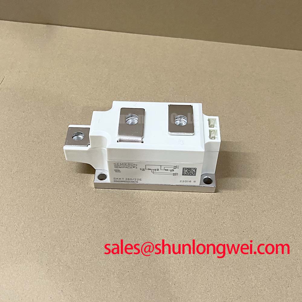
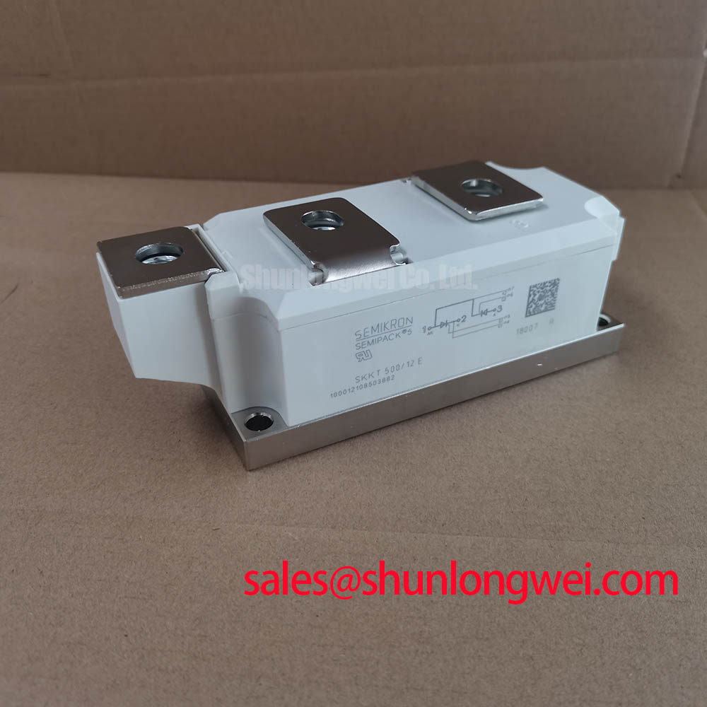
Trace each thyristor position through the bridge before reconnecting the power terminals and gate leads. The Semikron SKKT253/12E is a thyristor module used in controlled rectifier circuits. Record the anode, cathode, and corresponding gate connections from the module connection drawing; terminal position alone is insufficient when comparing assemblies with different internal circuits. The manufacturer's SEMIPACK thyristor and diode module range provides the relevant product-family context.
Official Specification: repetitive peak off-state and reverse voltage, 1200 V; average on-state current, 253 A at a case temperature of 85°C; surge on-state current, 7500 A for 10 ms; junction-to-case thermal resistance, 0.1 K/W per thyristor; isolation voltage, 3000 V. Apply these ratings with their respective datasheet test conditions. The isolation test rating does not establish continuous working voltage between the power circuit and heatsink.
Design Consideration: a six-pulse bridge requires correct phase order and firing sequence. A twelve-pulse arrangement additionally depends on the transformer phase relationship and bridge interconnection. Where parallel bridge groups use an interphase transformer, compare branch-current waveforms under the same load and firing command. Unequal transformer secondary voltages, connection resistance, or firing timing can contribute to unequal sharing. Kiloampere output is an assembly-level capability requiring verified current distribution and cooling.
When evaluating a high-current green hydrogen electrolyzer DC power rectifier, designers should verify the module's current waveform, losses, cooling conditions, and protection coordination against the complete power-stage requirements. The steady-state thermal resistance supports continuous-loss assessment; short load excursions require transient thermal impedance data and the actual pulse history.
Field Alert: Use the specified mounting and terminal torques, and keep the thermal interface uniformly applied before loading the bridge.
Preventing Spurious Faults: Harmonic Current Injection and Line Filter Guidelines for SKKT253/12E
Compare the firing command with the measured line-voltage reference and gate pulses when DC output fails to follow its setpoint. Design Consideration: with continuous current and negligible commutation overlap, the average output of a fully controlled bridge follows a cosine relationship with firing angle. Across a 0° to 150° evaluation range, increasing delay reduces average rectified voltage; operation beyond the rectifying region requires an appropriate energy source and valid commutation conditions.
Record AC line current alongside DC current rather than judging power factor from firing angle alone. Displacement, waveform distortion, and commutation overlap affect the measured result. Before changing a line filter, inspect its interaction with supply impedance and existing compensation equipment. Filter selection should follow measured harmonic currents and a system resonance assessment.
The comparison below separates the installed module's confirmed ratings from the information needed to assess SKKD380/12 as a related rectifier component.
| Comparison point | SKKT253/12E | SKKD380/12 |
|---|---|---|
| Device function | Controlled thyristor module | Diode rectifier module; different control function |
| Repetitive blocking voltage | 1200 V, Official Specification | Consult Datasheet |
| Average current and temperature condition | 253 A at 85°C case temperature, Official Specification | Consult Datasheet |
| Replacement assessment | Match gate circuit, terminal drawing, cooling, and protection | Assess circuit function before mechanical compatibility |
For assemblies containing a separate controlled auxiliary stage, SKKT-106B16E is another component for independent circuit assessment. Its gate requirements, terminal connections, and thermal limits must match that stage. The ROHM fast recovery diode range concerns a separate device class; recovery behavior becomes relevant where the surrounding circuit includes rapid commutation.
SKKT253/12E Circuit Protection & Reliability: Coordinating Fuse I²t
Compare the semiconductor fuse's total clearing I²t with the thyristor's permissible I²t at matching fault duration and initial junction temperature. Design Consideration: pre-arcing I²t alone omits the fuse's arcing contribution. Use the fuse manufacturer's coordination tables at the applicable circuit voltage and prospective fault current, then check peak let-through current against the module's surge conditions.
The 7500 A for 10 ms surge specification does not independently establish a fuse selection. Waveform shape, initial temperature, and the manufacturer's surge limits determine the applicable comparison. Protection coordination reduces fault stress; it cannot guarantee damage-free interruption of every short circuit.
Inspect snubber connections and bus joints before repeating an interrupted-load test. Minimize parasitic loop inductance to reduce transient overvoltage, then verify the measured terminal peaks against the blocking rating under representative operating conditions. Mastering Power System Dynamics provides supporting context for this assessment. Return the bridge to service only after checking firing synchronization, branch-current balance, terminal heating, and the selected fuse's coordination record.