Content last revised on September 15, 2026
SKKT162/14E Official Specifications
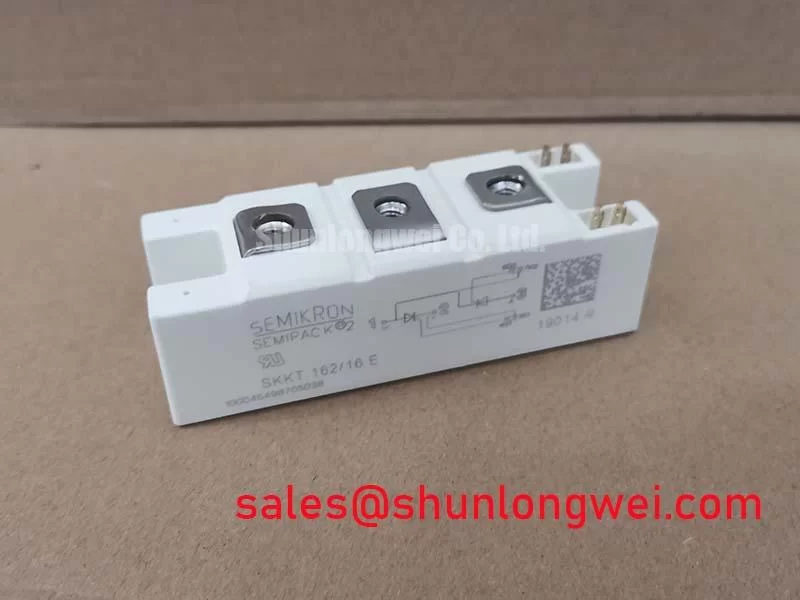
With the power circuit isolated and discharged, verify the terminal identification and check that the installed assembly matches the SKKT162/14E nameplate before reconnecting gate-drive leads or AC busbars. This Semikron thyristor module has an official repetitive peak reverse and off-state voltage rating of 1400 V, an average on-state current of 156 A at case temperature 85°C, and a maximum junction temperature of 125°C.
| Official Specification | Rating | Engineering Context |
|---|---|---|
| Repetitive peak reverse and off-state voltage | 1400 V | Official Datasheet Specification for repetitive blocking conditions |
| Average on-state current | 156 A at Tcase 85°C | Official Datasheet Specification for continuous conduction with suitable cooling |
| Non-repetitive surge on-state current | 5000 A, 10 ms, 125°C | Official Datasheet Specification for a short surge event |
| Maximum junction temperature | 125°C | Official Datasheet Specification defining the junction operating limit |
| Junction-to-case thermal resistance | 0.10 K/W per module | Official Datasheet Specification for heat transfer within the module |
| Isolation voltage | 3000 Vrms for 1 minute | Official Datasheet Specification between baseplate and power terminals |
Assembly Integrity & Layout Architecture: Implementing Gate Trigger Current Dynamics for SKKT162/14E
The SKKT162/14E is a thyristor module, so its external gate wiring deserves the same inspection discipline as the high-current path. Before commissioning, trace each gate and cathode reference from the firing board to the module terminals, confirm that the intended phase relationship is preserved, and inspect connector retention, conductor strain relief, and clearance from the main AC busbars. A loose low-current gate connection can create irregular triggering even when the power terminals remain mechanically sound.
Gate firing pulse rise time, holding support after the leading firing edge, and repeated firing-pulse strategies are system-level gate-driver subjects. The gate current values and timing limits for this module should be verified against the original Semikron device documentation and the existing controller design; they should not be inferred from the 1400 V and 156 A main-terminal ratings. Design Consideration: keep the gate return path paired closely with its associated gate conductor so inductive coupling from the main current loop is reduced during commutation.
In capacitor-switching and grid-tied reactive-power equipment, trigger consistency is especially relevant because unequal firing across a controlled AC topology can alter current sharing and transient behavior. Engineers evaluating a replacement installation should capture gate-to-cathode waveforms at the module terminals and compare them with a known-good channel under the same operating sequence. This provides evidence of pulse integrity without assigning a single cause to an observed firing anomaly.
The upstream semiconductor fuse must be coordinated using the system fuse manufacturer’s time-current and I²t documentation together with the protection information applicable to the installed circuit. The provided official specifications do not establish a fuse part number or I²t selection. Terminal fasteners should be tightened according to the module package documentation and the equipment manufacturer’s assembly procedure, with clean mating surfaces and correctly supported busbars.
Safety Interlock Note: Disconnect, lock out, and verify discharge of stored capacitor energy before touching the SKKT162/14E terminals or gate wiring.
SKKT162/14E Circuit Protection & Reliability: Calibrating AC Line Surge Immunity and Lightning Transients
The 1400 V VRRM/VDRM rating is an Official Datasheet Specification for repetitive blocking voltage, not a declaration that the module alone absorbs all utility disturbances. In grid-tied static var compensators and thyristor-switched capacitor banks, the actual voltage at the thyristor terminals depends on incoming line conditions, transformer behavior, capacitor-bank switching, busbar geometry, and the installed suppression network.
Design Consideration: assess AC surge protection as a coordinated assembly consisting of upstream protection, metal-oxide varistors where appropriate, RC snubbers where required by the commutation circuit, and physical routing that limits inductive coupling. IEC 61000-4-5 is commonly used as a system-level surge immunity reference, but it is not an individual certification claim for this thyristor module. The system engineer should validate terminal voltage waveforms under representative switching and surge-test conditions before setting protective-device values.
An RC snubber can influence the rate of reapplied voltage across a thyristor, while a MOV can limit selected transient conditions. Neither part should be chosen from the module’s voltage rating alone. Verify capacitor-bank parameters, expected switching transients, ambient conditions, fuse coordination, and the protective-device manufacturer’s derating data. For broader equipment-level context on power-semiconductor deployment and test planning, consult Industrial Applications.
Semikron’s SEMIPACK® thyristor and diode module information provides useful product-family context when reviewing package-level integration requirements. If a design review indicates a higher continuous current requirement, SKKT 250/14E can be examined as a related reference model, subject to a complete comparison of mechanical fit, electrical conditions, thermal design, trigger requirements, and system validation.
SKKT162/14E Thermal-Electrical Optimization: Non-Repetitive Surge On-State Current Practical Tuning
The official 5000 A non-repetitive surge on-state current rating applies to a 10 ms event at a stated junction condition of 125°C. It is a short-duration survivability rating, not a continuous operating current and not a permitted repetitive overload target. In service analysis, distinguish a documented surge event from recurrent overcurrent caused by capacitor inrush, line faults, delayed protection action, or abnormal commutation.
After a suspected fault event, examine the protection sequence before reapplying reverse voltage. Confirm the status of upstream fuses, suppression components, busbar insulation, terminal tightness, gate-driver outputs, and the cooling path. A power-circuit test should be planned around the equipment’s approved startup procedure, with measured voltage and current behavior compared against known operational conditions. The 125°C maximum junction temperature remains the official upper limit that the total electrical and thermal design must respect.
For reactive-power switching equipment, capacitor-bank energization can place unusual stress on the current path. Designers should verify that the installed thyristor switching sequence, protection coordination, and capacitor discharge conditions prevent repeated stress events from being treated as isolated surges. Regenerative-braking resistor circuits, where present elsewhere in an industrial drive, are a separate topology and must not be assumed to share the same protection arrangement as the SKKT162/14E controlled AC path.
The diode behavior and recovery characteristics relevant to a thyristor-based assembly should be assessed only from the applicable original circuit documentation and device data. Semikron’s CAL diode technology information is useful background when reviewing diode technology at a general level, but it does not substitute for module-specific verification.
Assembly Integrity & Layout Architecture: Implementing Junction-to-Case Thermal Resistance for SKKT162/14E
The SKKT162/14E has an official junction-to-case thermal resistance of 0.10 K/W per module. The module’s overall thermal performance also depends on a properly formed thermal interface in the installed equipment. Before mounting, inspect the heatsink for flatness concerns, residue, corrosion, raised burrs, or contamination that could prevent uniform baseplate contact. Apply the interface material according to the equipment procedure and tighten the mounting hardware in a balanced sequence so the module is seated without distortion.
Design Consideration: a thermal interface should be treated as a controlled contact layer rather than a compensator for a damaged heatsink surface. Uneven contact pressure can raise the thermal impedance between the case and heatsink, while excessive mechanical stress can compromise assembly integrity. The final mounting torque, screw specification, washer arrangement, and tightening sequence must be taken from the relevant package and equipment documentation rather than selected from generic module practice.
During thermal commissioning, measure heatsink temperature at repeatable locations and correlate it with actual load duty, airflow or liquid-cooling condition, and ambient enclosure temperature. If operating temperature rises unexpectedly, investigate the full thermal path, current waveform, trigger behavior, and cooling system condition instead of attributing the result to one component alone. The 3000 Vrms for 1 minute isolation rating is an Official Datasheet Specification between baseplate and power terminals; system insulation coordination, enclosure design, and maintenance procedures remain separate responsibilities of the equipment design.