

Content last revised on September 18, 2026
SKKD380/16 Thermal and Electrical Integration: Rectifier Path Verification and Temperature-Dependent Operation
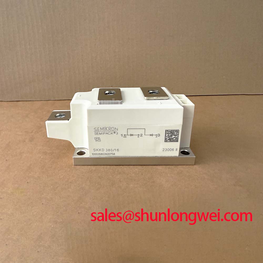
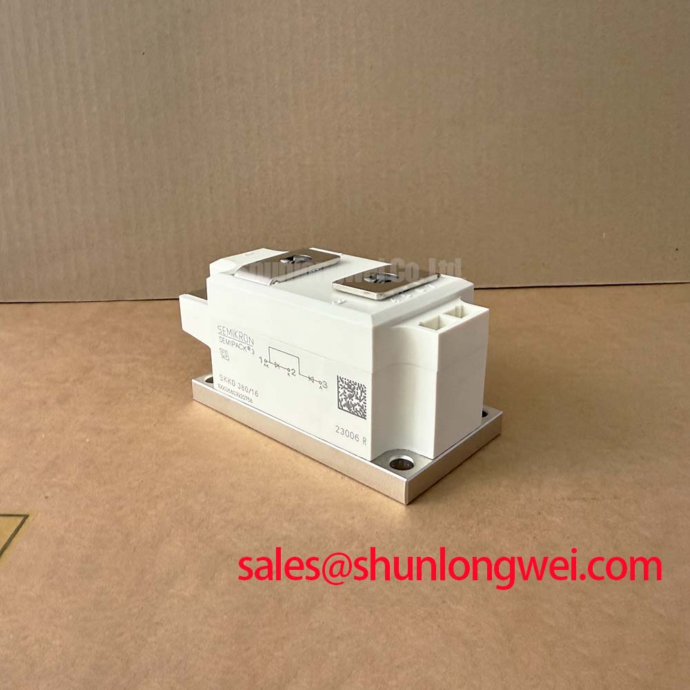
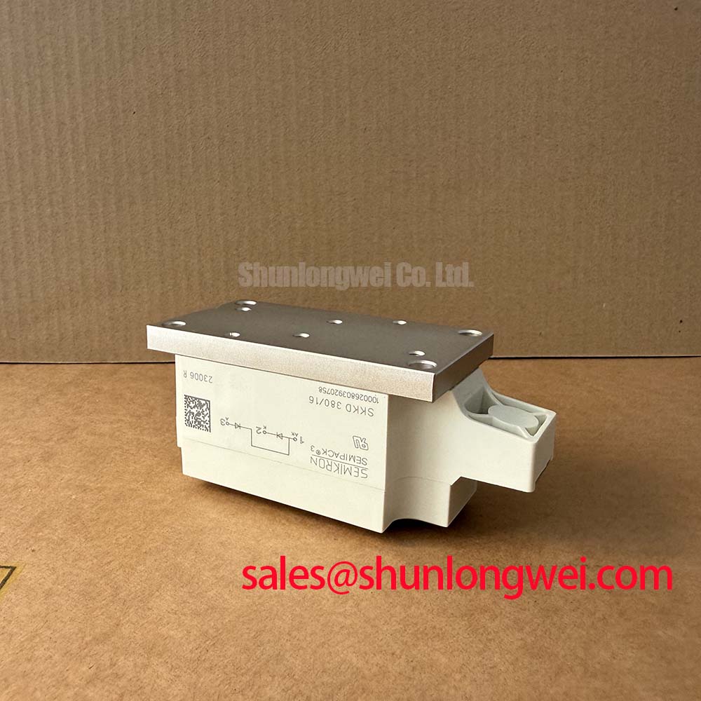
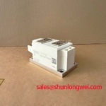
Before energizing a replacement assembly, verify the nameplate against the rectifier bill of materials and confirm that the required device ratings are a 1600V voltage rating with a stated current rating of 380A. The supplied product data identifies SKKD380/16 as a Semikron Diode Module in a Semipack housing. These are the declared official specifications for this product record; terminal arrangement, polarity, mounting hardware, thermal resistance, surge capability, fuse coordination, and internal circuit configuration must be checked against the applicable original Semikron documentation before installation.
| Parameter | Declared Value | Classification |
|---|---|---|
| Product model | SKKD380/16 | Official product identification |
| Manufacturer | Semikron | Official product identification |
| Rated voltage | 1600V | Official Specification |
| Rated current | 380A | Official Specification |
| Housing | Semipack | Official Specification |
| Product category | Diode Module | Product classification |
The practical starting point is to establish whether the installed rectifier position uses the SKKD380/16 as a diode path or as part of a larger bridge arrangement. The SKKD380/16 is identified as a diode module, so gate trigger current, gate pulse rise time, holding current, latching current, and firing pulse sequence are not applicable characteristics of this module. Where controlled thyristor stages are present elsewhere in the converter, a service engineer should trace the cabinet wiring and compare each power and control connection with the original equipment schematic before connecting a gate driver or firing board.
Where the surrounding converter includes controlled thyristor stages, firing pulse integrity remains an Engineering Recommendation for the complete system rather than an official specification of this module record. The relevant checks are pulse arrival at the intended terminal, repeatability between parallel control channels, isolation from power conductors, and correct timing relative to the AC supply waveform. A distorted pulse, intermittent connector, or incorrectly referenced measurement probe can produce observations that resemble a semiconductor fault while the underlying issue is in the firing transformer, driver supply, control board, or wiring harness.
Thermal performance must be evaluated from the actual interface and operating waveform. The declared 380A rating is not, by itself, a thermal model for a particular heatsink, busbar arrangement, ambient condition, or duty cycle. Designers should verify the original datasheet limits, the mounting surface flatness, the specified mounting method, and the measured case temperature during representative operation. If multiple current paths are paralleled in a rectifier cabinet, static and dynamic current sharing should be confirmed from measured current waveforms rather than assumed from nominally similar cable lengths or device ratings.
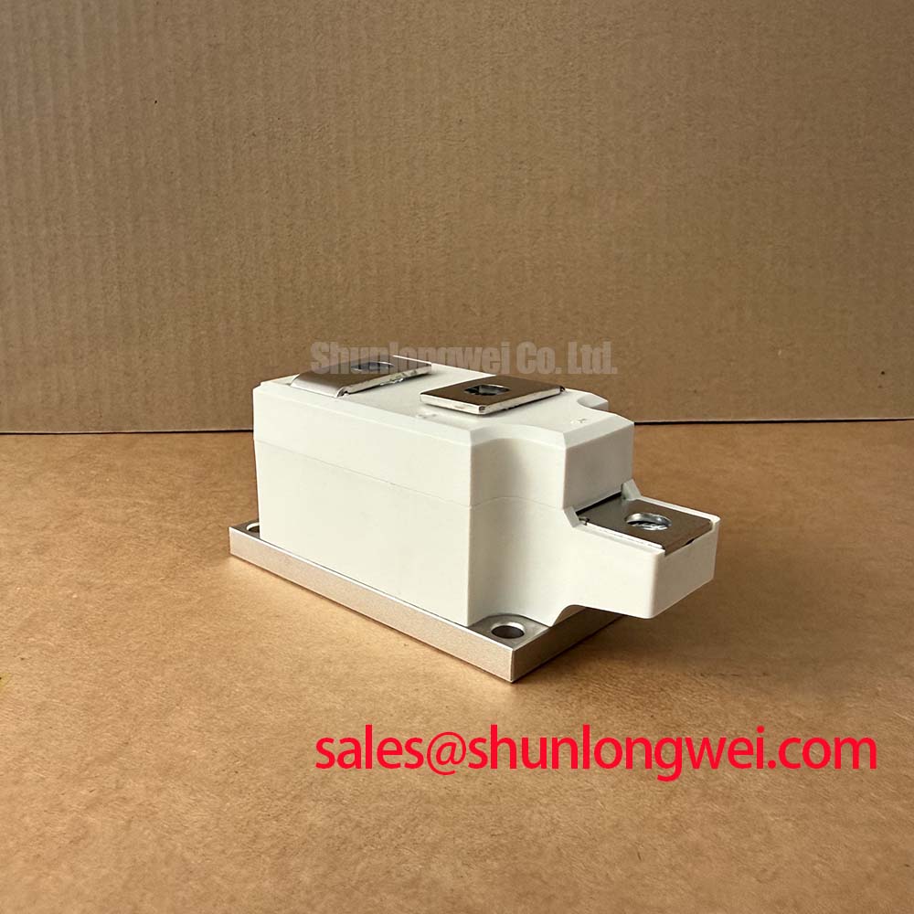
The Semipack format should be handled as a power assembly with defined mechanical and electrical interfaces, not as a generic two-terminal device. The system integrator should confirm the terminal designations, creepage conditions within the existing enclosure, conductor contact area, and the approved fastening details from the original documentation. 🔧 Bench Diagnostic: Isolate stored energy and verify the DC link is discharged before removing or reconnecting any high-current terminal hardware.
Fuse coordination also requires model-specific source data. No fuse I²t limit, recommended fuse type, or permissible mounting torque is included in the supplied official parameter set. It would therefore be unsafe to publish a fixed fuse selection or torque value as an SKKD380/16 requirement. A suitable verification workflow compares the installed fuse data, prospective fault current, conductor geometry, and the original equipment manufacturer’s semiconductor protection specification.
Field Diagnostics and Commissioning: Non-Repetitive Surge Current Boundaries in SKKD380/16 Topologies
Commissioning after a rectifier fault should begin with de-energized isolation testing of the module terminals and adjacent buswork. Compare the observed conduction paths with the known circuit diagram and with a known-good assembly where one is available. The objective is not to force a universal meter reading onto the part, because test instrument current, lead resistance, circuit shunts, snubber branches, and parallel semiconductor paths can all alter the result. Instead, identify unexpected low-resistance paths, open paths, or asymmetric results and then isolate external connections as required by the service procedure.
The supplied information does not state an ITSM value for a sinusoidal 10 ms half cycle. Consequently, no numeric non-repetitive surge current capability can be attributed to SKKD380/16 from the declared information. The same restriction applies to peak overload duration and the junction temperature recovery window following a fault. Engineers should obtain the applicable original manufacturer data before deciding whether an event was within a permitted transient boundary or whether the module requires replacement and the surrounding system requires investigation.
In a high-current green hydrogen electrolyzer DC power rectifier, a disturbance may involve AC supply imbalance, transformer saturation effects, control timing loss, DC-side faults, inadequate cooling flow, or a fault external to the semiconductor module. A single symptom should not be treated as proof of one cause. Record the pre-fault operating state, protective relay indications, fuse condition, cooling status, phase currents, DC output current, and any controller event log. That evidence supports a safer decision than replacing a module without checking the initiating condition.
Before reverse voltage is reapplied, the maintenance team should confirm that the affected heatsink and adjoining conductors have returned to a safe measured condition under the equipment service rules. The voltage rating of 1600V is an Official Specification, but it does not establish a complete system transient margin. As a Design Consideration, transient suppression components such as MOV networks, RC snubbers, and DC bus capacitors must be evaluated in the installed topology, with their clamping behavior verified against measured voltage conditions and the system’s permissible limits.
For background on how power semiconductors are applied across demanding industrial conversion systems, consult Industrial Applications. That resource can help frame system-level evaluation, while the original equipment documentation remains the controlling reference for this specific module location.
Assembly Integrity and Layout Architecture: Power Factor and Harmonic Control Around SKKD380/16
AC-to-DC rectifier behaviour depends on the full topology, including transformer impedance, phase arrangement, source waveform, firing strategy where controlled devices are present, DC load dynamics, filter components, and feedback control. A firing angle range from zero to 150 degrees is a system control condition, not a declared SKKD380/16 characteristic. It is therefore not valid to derive a power factor curve, reactive power demand, or harmonic spectrum from the supplied module ratings alone.
Where a controlled rectifier bridge operates across changing firing angles, delayed conduction can change the relationship between source voltage and line current. The resulting displacement factor and harmonic content should be measured at the installation using suitable three-phase instrumentation and compared with the equipment’s design requirements. Engineers should also check whether control settings have been changed following maintenance, as a commissioning mismatch can affect process output and transformer loading without indicating a module defect.
Busbar layout is equally important in high-current conversion equipment. As a Design Consideration, keep forward and return current paths physically close and geometrically consistent to reduce loop inductance that can contribute to transient overvoltage during commutation. The system engineer should validate peak voltage conditions at the installed power terminals with an appropriate high-voltage measurement method, particularly after any change to busbar length, capacitor placement, snubber wiring, or module mounting position.
Mechanical assembly should preserve clean, flat electrical contact surfaces and the original conductor stack order. Do not assume that a similar Semipack module has identical terminal positions or mounting requirements. Semikron’s SEMIPACK® thyristor and diode module information provides product family context, but the exact variant documentation must be matched to the installed part number.
A potential equipment evaluation example is a high-current green hydrogen electrolyzer DC power rectifier, where stable DC output and controlled thermal loading are central integration concerns. This example does not establish that SKKD380/16 is dedicated to that application. Compatibility should be verified through the original electrical drawings, required blocking voltage, current waveform, cooling arrangement, protection architecture, and terminal compatibility.
When an existing design review calls for a different current or voltage class, SKKT500/08E can be considered as a separately documented comparison item. It is not a universal direct substitution for SKKD380/16. Circuit function, terminal configuration, trigger interface where applicable, insulation requirements, thermal conditions, and protection coordination all require independent engineering verification.
Transient Dynamics and Electrical Design: I²t Protection Coordination for SKKD380/16
A dead-short event is governed by the available source energy, transformer characteristics, upstream protection response, cable impedance, busbar inductance, and fault location. The product information supplied here does not provide an I²t withstand rating, fuse pre-arcing I²t limit, clearing I²t limit, or a manufacturer-approved coordination table for SKKD380/16. No numerical fuse-clearing energy calculation should therefore be presented as an official safe operating limit for this model.
The correct protection review compares time-current curves and energy data from the actual semiconductor fuse manufacturer with the verified module withstand data and the calculated or measured prospective short-circuit current of the installation. This is an Engineering Recommendation. The review must include the complete protective path, because a fuse selected only by continuous current rating may not coordinate correctly with a semiconductor device under a fast fault condition.
MOV-based overvoltage suppression should also be assessed as part of the complete fault and commutation network. An MOV can limit a transient only within its own energy and clamping capability, and its effectiveness depends on wiring inductance, placement, repetitive exposure, and interaction with other suppression elements. Designers should verify the transient waveform at the relevant terminals under controlled test conditions rather than assuming that the presence of an MOV guarantees compliance with the 1600V module voltage rating.
Semiconductor diode technology can influence reverse recovery and rectifier behaviour, but no internal chip technology is stated for SKKD380/16 in the supplied data. For general technology context, Semikron publishes information on CAL diode technology. That reference should not be used to assign undocumented recovery, switching, surge, or thermal values to this particular module.
After protection work, commissioning should proceed through the equipment manufacturer’s controlled sequence. Verify phase order, intended terminal connections, protective interlocks, cooling operation, and measured voltage and current waveforms before restoring full process duty. This approach keeps the SKKD380/16 evaluation tied to its declared 1600V, 380A, and Semipack identity while leaving system-specific protection limits to verified documentation and test evidence.