Content last revised on October 3, 2026
SKKD380-08 Identification and Replacement Checks
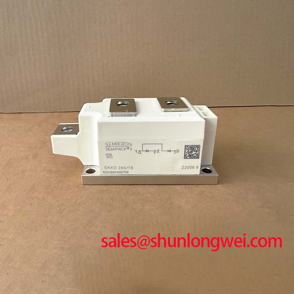
Before energizing a replacement, isolate the rectifier, record the original terminal arrangement, inspect the housing for cracks or deformation, and verify the specified ratings of 800 V and 380 A against the equipment documentation. The Semikron SKKD380-08 is a high current dual-diode module in the Semipack package. These ratings do not, by themselves, define the allowable current in every bridge arrangement, cooling condition, pulse profile, or fault condition.
For a high current green hydrogen electrolyzer DC power rectifier, the module should be assessed as one part of the complete commutation, protection, cooling, busbar, and control system. The system integrator should confirm the original circuit topology and terminal designation before installing a replacement. A module with the same voltage and current markings can still require different mechanical clearances, fuse coordination, and thermal interface treatment.
| Manufacturer | Semikron |
| Part number | SKKD380-08 |
| Device category | Dual-diode module |
| Voltage rating | 800 V |
| Current rating | 380 A under specified conditions |
| Package | Semipack |
Benchtop Waveform Tuning: Mitigating Stress via Dynamic Voltage Sharing and RC Damping on SKKD380-08
Initial bench work should begin with the power stage fully isolated and discharged. Measure the cold state of the external circuit rather than applying a test voltage immediately. Check the resistance and continuity of the connected busbars, fuses, snubber branches, transformer windings, and control wiring against a known good phase where possible. A low resistance reading across a semiconductor power path is not sufficient to identify a healthy or damaged device; the result depends on the measurement direction, connected components, and the meter method.
The SKKD380-08 has a specified voltage rating of 800 V and a current rating of 380 A under specified conditions. During waveform work, these figures should be treated as device identification and rating boundaries, not as a complete switching prescription. The actual voltage stress must be checked at the module terminals with suitable probes during controlled commissioning. Designers should verify transient peaks against the rectifier DC link, commutation inductance, transformer leakage, busbar geometry, and the selected protection network.
In a high current bridge, an RC snubber is normally evaluated to control unwanted voltage ringing and excessive commutation stress. The resistor and capacitor values are system determined. They should be selected from measured waveform behavior, capacitor pulse capability, resistor energy handling, repetitive duty, and the switching or line frequency of the actual rectifier. The SKKD380-08 product data supplied here does not provide an RC network value, so a fixed snubber prescription would not be technically justified.
Use a differential high voltage probe and a current probe when examining the commutation interval. Look for ringing that changes with busbar position, load current, transformer operating point, or snubber connection. If the waveform differs substantially between bridge positions, inspect conductor symmetry, terminal pressure, fuse condition, and the physical path of the snubber return. A saturable reactor may be considered where the system requires control of current rise, but its core behavior, saturation point, thermal condition, and fault response must be validated by the rectifier designer.
The Semikron SEMIPACK® Thyristor / Diode Modules reference provides useful manufacturer-level context for the product family. It should be read together with the exact electrical and mechanical documentation for the installed circuit. A family page should not be used as a substitute for the specific terminal drawing, thermal data, or fuse coordination information required for a service decision.
When a replacement is being considered, the SKKH273/18E can be reviewed as a separate Semikron device for compatibility assessment. It is not an automatic substitute for the SKKD380-08. Voltage, current, package geometry, terminal arrangement, cooling interface, circuit role, and the original equipment manufacturer’s approval must all be checked before any change is made.
🔧 Field Alert: Do not reconnect the module until the equipment is isolated, the capacitor bank is discharged, and every terminal has been matched to the original circuit documentation.
Field Diagnostics & Commissioning: Diode Peak Reverse Recovery Current and Soft Recovery in SKKD380-08 Topologies
Reverse recovery evaluation is most useful after the basic mechanical and static electrical checks have passed. Inspect the external semiconductor connections for discoloration, looseness, uneven contact pressure, and signs of local heating. Check the associated fuse, busbar, transformer, snubber, and measurement wiring before attributing a commutation waveform to the module. A damaged fuse or altered conductor path can change the measured current and voltage behavior even when the semiconductor itself is unchanged.
Reverse recovery current and recovery time are not stated in the supplied product parameters for this page. They should therefore be obtained from the applicable Semikron technical documentation or measured in the actual circuit under controlled conditions. The observed peak depends on line impedance, transformer leakage, commutation overlap, load current, temperature, circuit inductance, and the behavior of other devices in the bridge. A single oscilloscope capture should be treated as a diagnostic observation rather than a universal rating.
For commissioning, compare equivalent bridge positions under the same operating condition. Record the voltage across the device, the current in the relevant conductor, the switching timing of other devices where applicable, and the temperature at the module mounting interface. A waveform with higher ringing or a visibly different recovery profile may indicate impedance imbalance, probe placement effects, a changed snubber path, fuse aging, or a device condition that requires further testing. Confirm the result against a known good phase before replacing hardware.
Soft recovery is relevant to commutation stress and conducted or radiated interference, but its practical effect is controlled by the complete topology. The design team should review the line reactor, interphase transformer where used, DC bus arrangement, wiring loop, and the placement of damping components. The SKKD380-08 rating of 800 V does not establish a permitted reverse recovery peak or a guaranteed EMI result. EMC performance belongs to the assembled rectifier and its installation, not to the semiconductor module alone.
During field replacement, retain the original phase relationship and cable routing. Avoid extending high current conductors for convenience, since additional loop area can alter commutation behavior. If a replacement produces a different waveform, verify the mechanical seating, terminal contact, cooling interface, fuse type, and snubber connection before concluding that the device is incompatible.
SKKD380-08 Thermal Electrical Optimization: Interphase Transformer Current Balancing Practical Tuning
Six pulse and twelve pulse rectifier arrangements require careful phase identification and current path verification. The SKKD380-08 may be evaluated in high current DC rectifier assemblies, including electrolyzer power conversion equipment, but the module specification supplied here does not define a particular bridge configuration or guarantee a specific DC output. The original schematic should be checked for phase sequence, device orientation, transformer connection, freewheel paths, and the location of measurement points.
In a twelve pulse system, an interphase transformer can help combine rectifier sections and influence current sharing. Its performance depends on winding balance, leakage characteristics, magnetic operating point, connection polarity, and the behavior of both bridge groups. When one section carries more current, inspect the transformer connections and phase sequence before changing semiconductor hardware. Use matched measurement methods on each branch and compare current waveforms at the same load condition.
Thermal checks should cover the complete path from the module mounting surface through the heatsink, forced air or liquid cooling system, busbar joints, and enclosure. The Semipack package is the package designation for this model, while the supplied data does not specify a thermal resistance value, mounting torque, heatsink type, or cooling medium. Those values must be taken from the relevant mechanical and thermal documentation rather than inferred from the package name.
When installing the unit, clean the mating surfaces according to the equipment service procedure and apply the specified interface material consistently. The mounting hardware, clamping sequence, contact flatness, and terminal tightening method should follow the applicable Semikron documentation and the original assembly practice. Designers should verify temperature rise at the module and at each high current connection during commissioning, because a satisfactory no load inspection cannot confirm current balance under operating load.
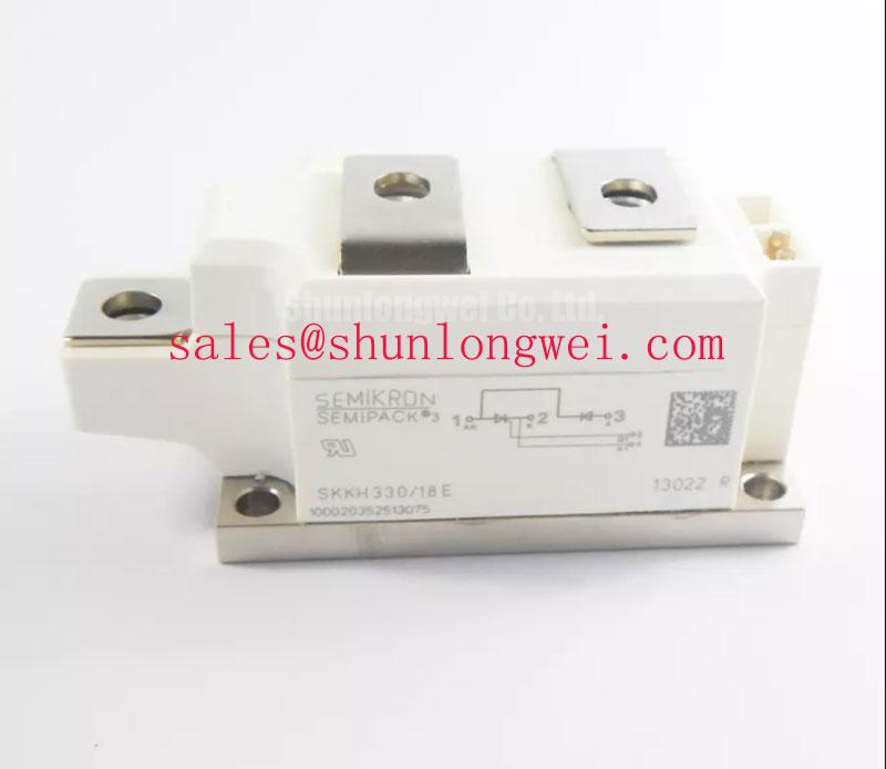
For an associated rectifier stage, engineers may also review the SKKH330/08E as a separate complementary device reference. This link does not establish interchangeability. The electrical ratings, circuit role, package dimensions, control requirements, and protection coordination must be compared with the installed design before procurement or substitution.
Where vibration or thermal cycling is present, examine busbar supports, fastener retention, cable strain relief, and the module mounting plane during scheduled maintenance. Mechanical movement can change contact resistance and introduce waveform variation. If the system operates in a cold enclosure, confirm the controller, sensors, fans, heaters, and cooling circuit reach their intended operating condition before applying full rectifier load. No cold start response specification is provided for this module alone.
SKKD380-08 Thermal Electrical Optimization: Semiconductor Protection Fuse Selection in Practical Tuning
Fuse selection for the SKKD380-08 must be based on the actual fault path, prospective current, clearing behavior, repetitive load profile, and the semiconductor manufacturer’s coordination data. The supplied product parameters identify the module as a 380 A, 800 V Semipack device, but they do not include a fuse I²t value, a fuse class, a peak let through current, a short circuit withstand limit, or a coordination table. These missing values must be confirmed from the relevant device and fuse documentation.
During a protection review, identify whether the fuse is protecting an individual bridge path, a transformer secondary, a DC output branch, or the complete rectifier assembly. Confirm the fuse voltage rating, prospective fault current, interrupting capability, cooling condition, mounting orientation, and conductor arrangement. The fuse must interrupt the fault before the semiconductor and surrounding conductors are exposed to energy beyond their verified limits. This is a coordination exercise, not a conclusion based on the module current marking alone.
The practical comparison involves the fuse clearing energy and the semiconductor withstand capability under the specified fault waveform. Engineers should use the manufacturer’s published I²t data and the fuse supplier’s tested clearing curves for the intended voltage and circuit condition. If the installation uses a transformer, the available fault current and decay behavior may differ materially from a stiff laboratory supply. The actual bus inductance, transformer impedance, parallel paths, and fuse temperature should be included in the review.
Inspect failed protection components as part of the diagnosis. A blown fuse may follow a semiconductor short circuit, an external bus fault, a cooling failure, a wiring error, or a transient event. Replace the fuse only after checking the module and the surrounding circuit for low impedance paths, damaged insulation, carbonized surfaces, loose connections, and altered snubber components. A replacement fuse with a similar current marking is not automatically suitable if its voltage, speed, I²t, physical format, or coordination behavior differs.
The IGBT Design & Integration technical reference can provide broader guidance on power circuit integration, thermal management, and protection principles. The SKKD380-08 is a dual-diode module rather than an IGBT, so its specific commutation and protection requirements must remain tied to the applicable Semikron documentation and the measured rectifier topology.
Before returning a repaired high current electrolyzer rectifier to service, verify phase sequence, insulation condition, cooling operation, fuse coordination, terminal security, waveform symmetry, and controlled load response. The final acceptance limits should come from the equipment design authority and the applicable component documentation.