Content last revised on October 7, 2026
Reverse Recovery Charge (Q_rr) & Commutation Turn-Off Snubber Loss Optimization
With the soft starter isolated and its stored energy discharged, check the installed module’s terminal layout and nameplate before removing it. The supplied product record identifies the SKKH330-18E as a Semikron thyristor/diode module in a Semipack case, with recorded ratings of 800.0 V and 3301.0 A. Those figures require confirmation against the exact manufacturer datasheet and the installed unit before they are used as replacement limits. The model suffix must not be treated as a substitute for a verified voltage rating.
In a high-voltage three-phase motor solid-state soft starter, inspect the circuit drawing before attributing a commutation problem to the SKKH330-18E. Identify the module’s anode, cathode and gate connections on the equipment schematic, then trace the associated protection network. A thyristor normally ceases conduction when its current falls below the holding condition and sufficient blocking time follows. Diode reverse recovery is a separate behavior; whether it contributes to a measured commutation transient depends on the actual current path.
Reverse recovery charge, peak reverse recovery current and recovery time should be taken from the applicable manufacturer datasheet if the installed circuit makes those diode characteristics relevant. They are not provided in the supplied product record, so none can be assigned to this module here. During a controlled test, compare voltage across the device and current through its branch with a known-good phase under the same operating conditions. A changed waveform may warrant inspection of the device, snubber, wiring and load together; it does not identify a single failed part on its own.
As a Design Consideration, review snubber losses alongside the measured commutation waveform rather than reducing capacitance solely to lower heat. The system engineer should verify peak device voltage, snubber temperature and the complete soft-starter operating sequence before approving a change. Semikron Danfoss describes the wider SEMIPACK thyristor and diode module product line; that product-line description does not establish unlisted SKKH330-18E recovery values. Its bare-die technology information is likewise background material, not evidence that a particular diode technology is fitted inside this module.
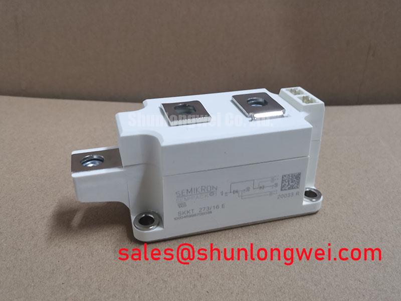
When tracing the complete power path, a technician may also encounter a separate module such as the SKKT 106B08E elsewhere in the equipment. Its circuit position and ratings must be established from that machine’s schematic; the part numbers alone do not establish that the modules perform interchangeable roles.
Baseplate Thermal Resistance (R_th(j-c)) & Mounting Clamping Torque Calibration
Before fitting the replacement, photograph the terminal connections, mark each conductor to match the schematic and examine the heatsink contact area. Remove old interface material using a method suitable for the heatsink and module surfaces. Check for raised burrs, debris and uneven contact that could prevent the case from seating. The supplied record specifies a Semipack case but provides neither a baseplate material nor a junction-to-case thermal resistance value; neither should be assumed from the package name.
As a Design Consideration, apply thermal interface material in a uniform layer that fills surface irregularities without holding the module away from the heatsink. Seat the case evenly and tighten its fasteners in the sequence and to the torque specified for the exact module and hardware. No SKKH330-18E mounting or terminal torque is available in the supplied record. Guessing from bolt size risks an unreliable thermal joint or damage to the case and terminals.
⚠️ Maintenance Note: Recheck heatsink cleanliness and contact temperature during scheduled maintenance, because a clear fan path cannot compensate for poor module-to-heatsink contact.
Compare phase temperatures only under comparable motor loading and cooling conditions. An elevated case or terminal temperature may justify checking fan operation, heatsink fouling, interface condition and connection tightness before assigning the cause to junction heating. Guidance on organizing measurements and repeat checks is available in the Field Engineer’s Handbook. For equipment exposed to temperature swings, inspect the enclosure for moisture and signs of condensation before energizing it; the module’s unlisted environmental limits still need confirmation from its documentation.
Surge Energy Dissipation and Clamping Voltage Margins for 1600V/1800V Thyristors
The voltage classes in this heading describe a protection-design question, not a rating established for the SKKH330-18E. In particular, they must not override the supplied record’s 800.0 V entry. Before evaluating this part for a soft starter, obtain the exact manufacturer datasheet, reconcile its voltage designation with the product record and compare the confirmed blocking ratings with the equipment’s measured and specified voltage stresses. If the documents disagree, leave the selection unresolved rather than inferring a rating from the model name.
For surge protection, trace where each metal oxide varistor and RC snubber connects relative to the thyristor terminals. Inspect for disconnected leads, heat discoloration and changed component markings, then compare the arrangement with the original equipment drawing. As a Design Consideration, protection must limit the voltage presented to the device under the system’s defined surge conditions while remaining compatible with normal operation. The equipment designer must determine component ratings and verify the resulting waveforms; a module listing alone cannot establish a safe clamping voltage or surge-energy margin.
Keep the test requirement separate from a compliance claim. A system surge test and the suitability of an individual semiconductor are different questions, and no equipment-level surge or EMC certification follows from the SKKH330-18E part number. Where the original protection parts are missing or altered, record their markings and circuit locations before requesting a design review rather than selecting replacements by appearance.
Non-Repetitive Surge On-State Current (I_TSM) & Post-Fault Blocking Capability
After a fuse operation or a failed motor start, isolate the starter and record which phase and protective device operated. Inspect the module terminals and nearby conductors before performing the cold checks permitted by the equipment service procedure. Compare the suspected branch with the other phases, accounting for parallel components that can affect an in-circuit reading. A static check is useful for triage, but it cannot by itself prove that a thyristor will regain its specified blocking capability after a surge.
The supplied record does not state the SKKH330-18E non-repetitive surge on-state current, its test conditions, or a fuse-coordination I²t value. Obtain those figures from the exact manufacturer datasheet and the fuse documentation before assessing a fault event. The waveform duration, starting junction temperature and subsequent voltage reapplication matter to that assessment; a nominal current rating is not a substitute for the surge specification.
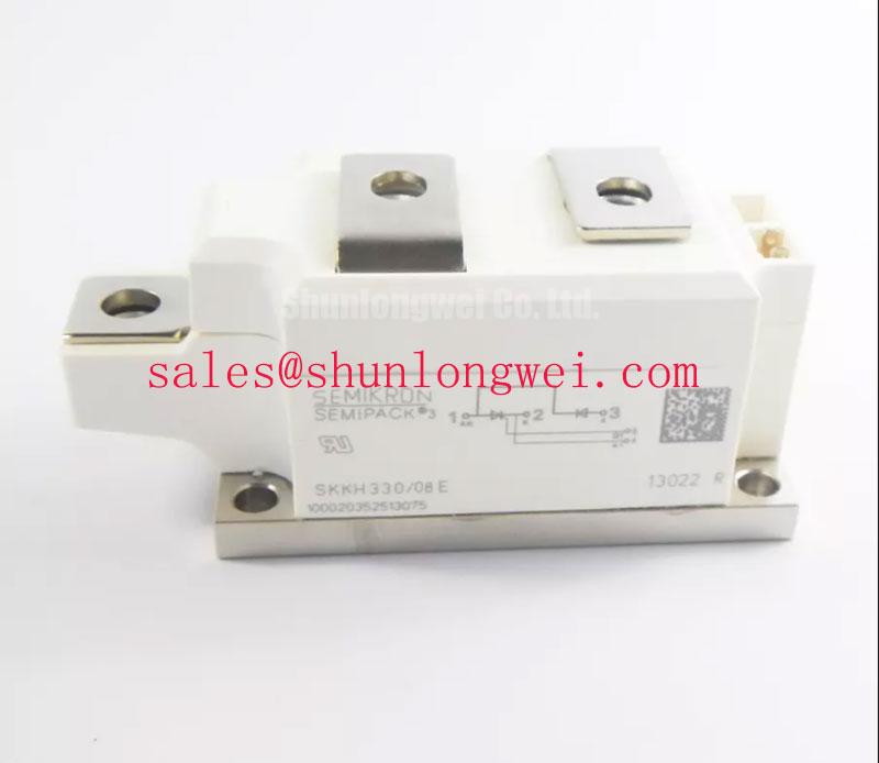
For maintenance purchasing, SKKH330/08E can be included in a document comparison, but it is not a confirmed substitute. Check its manufacturer ratings, circuit configuration, terminal positions, mounting details and gate-drive requirements against the installed design before considering any change. For the SKKH330-18E, keep the machine out of service until the conflicting voltage information has been resolved and the post-fault checks required by the equipment procedure are complete.