Content last revised on September 14, 2026
SKKT 106B08E Thermal Electrical Optimization: Critical Rate of Rise of Off State Voltage Practical Tuning
The Semikron SKKT 106B08E is a dual thyristor module specified for 800 V repetitive peak reverse and off state voltage. Its stated non repetitive peak reverse voltage is 900 V. In a medium frequency induction melting or hardening furnace, these ratings must be checked against the rectifier bridge voltage, commutation transients, transformer leakage behavior, and the switching conditions produced by the complete power stage.
The official average on state current is 106 A at a case temperature of 85 °C, while the RMS on state current is 180 A. These values are device ratings, not an automatic guarantee of the same current in every furnace design. Conduction angle, cooling method, current waveform, ambient temperature, busbar layout, and thermal interface quality all influence the applicable operating point. Designers should verify the junction temperature calculation using the actual load waveform rather than relying on the nameplate current alone.
The specified critical rate of rise of off state voltage is 1000 V/µs, Class E. This value is relevant when examining unintended thyristor triggering during commutation or voltage recovery. An RC snubber can be evaluated to control the local voltage transition, but resistor and capacitor values must be selected from the measured circuit impedance, repetitive voltage waveform, pulse energy, and allowable dissipation. A series saturable reactor may also be considered where the system requires control of current rise during a transient. Its suitability remains a system level decision that should be confirmed with oscilloscope measurements.
When tuning the protection network, probe the voltage directly at the module terminals with a suitable differential probe and compare the result with the control timing signal. Long measurement leads can add ringing that is not present at the semiconductor. The gate circuit should be examined at the gate and cathode terminals, not only at the output of the isolated driver. The maximum gate trigger current is 150 mA, and the maximum gate trigger voltage is 3 V, both listed as official specifications. These figures should be coordinated with the actual pulse width, pulse repetition method, gate wiring, and isolation circuit.
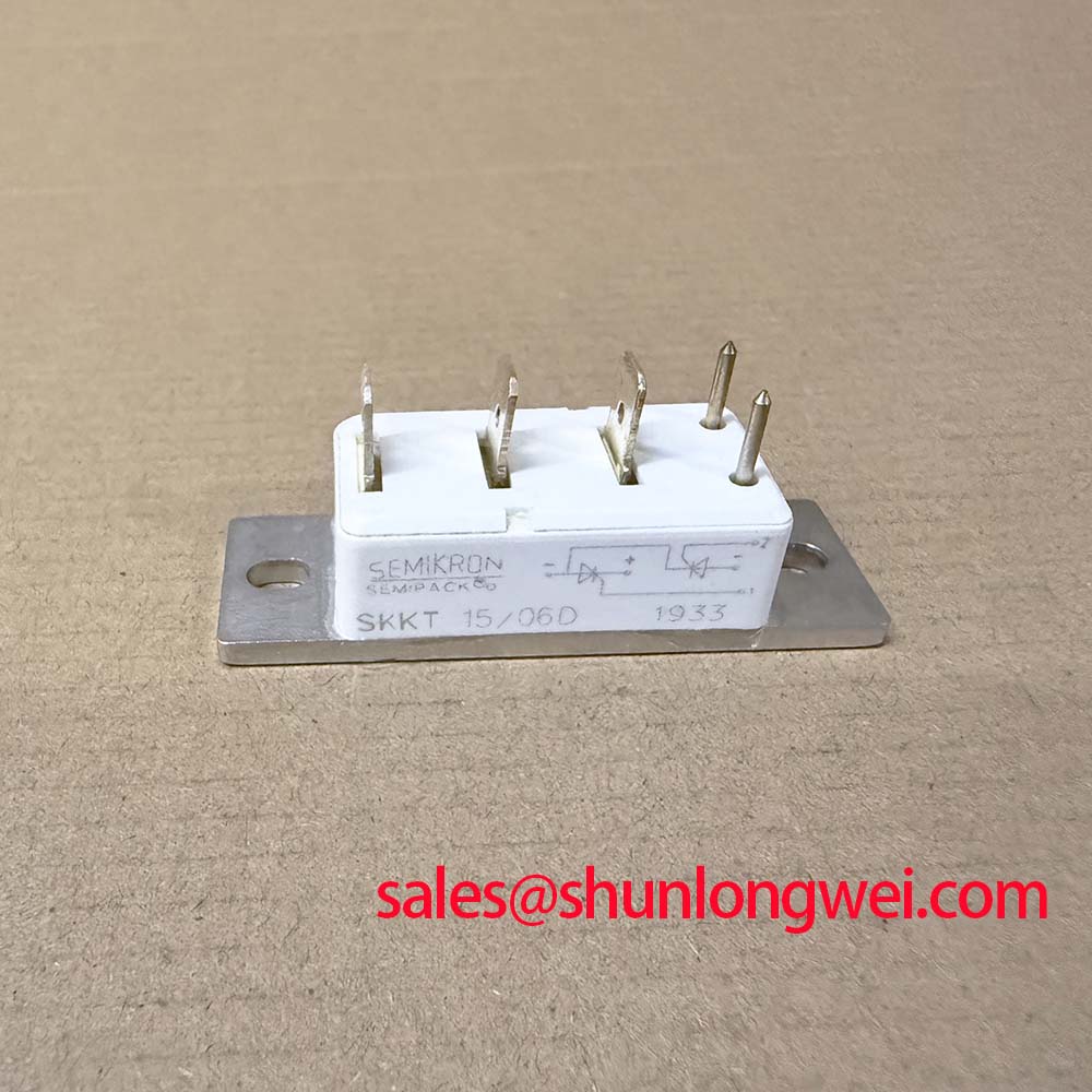
The module uses a SEMIPACK 1, Case A 48 housing with stated dimensions of 93 × 20 × 30 mm. Confirm the terminal arrangement from the original manufacturer documentation before connecting an unfamiliar installation. Mounting pressure, flatness, thermal compound application, and tightening procedure affect heat transfer and mechanical stress. The applicable Semikron installation instructions should be used for the final mounting torque rather than applying a generic value.
Safety interlock note: Disconnect and verify the DC link is discharged before removing gate leads, power terminals, or measurement probes.
Benchtop Waveform Tuning: Mitigating Stress via Short Circuit Withstand Limits and Coordination
The SKKT 106B08E lists a surge on state current of 2250 A at a junction temperature of 25 °C and a 10 ms condition. It also lists an I²t value of 25000 A²s under the same stated test condition. These are important reference points for semiconductor fuse coordination, but they should not be interpreted as permission to expose the module repeatedly to a dead short. Surge capability is dependent on pulse duration, initial junction temperature, circuit inductance, current waveform, and recovery conditions.
For a furnace rectifier, the protective fuse should be evaluated against the complete prospective fault current and the clearing behavior of the selected fuse. The fuse manufacturer’s semiconductor protection data and the applicable Semikron coordination table should be checked together. The comparison should account for the energy let through before interruption, the peak current reached during clearing, and the voltage generated by the opening circuit. If the available coordination data does not cover the exact bridge arrangement, the system engineer should validate the protection with a controlled fault study or an appropriately rated test setup.
A benchtop waveform review should begin with the bridge disabled and the measurement system verified. Inspect the main terminals for looseness, discoloration, cracked insulation, and signs of uneven contact pressure. Then confirm that the fuse, busbar, transformer, and current limiting elements match the approved schematic. During a controlled low energy test, observe the current transformer signal and the voltage across the module. A sudden change in waveform can indicate a protection mismatch, wiring problem, commutation disturbance, or a damaged device; it should be compared with a known good phase rather than assigned to one cause without measurement.
The gate circuit deserves separate attention during fault analysis. The listed IGT and VGT maximum values are 150 mA and 3 V. A short trigger pulse that looks acceptable at the driver output may be inadequate at the module because of optocoupler output resistance, gate lead inductance, cathode movement, or common mode voltage. A pulse train can be considered where the control architecture supports it, but the pulse amplitude, duration, isolation withstand, and timing must be verified on the installed assembly. The SKKT 106B08E should not be assumed to include an internal gate driver or fault logic.
In a system containing a separate rectifier or front end, engineers may review related Semikron devices such as SKKH330/08E as a neutral reference for topology planning. This is not a substitute recommendation. Voltage rating, current waveform, package, terminal arrangement, gate requirements, and thermal performance must be checked independently before considering any cross model application.
Thermal recovery after a high current event also requires attention. The stated Rth(j-c) is 0.35 °C/W per thyristor, but the actual case temperature depends on the heatsink, airflow, contact surface, thermal interface, and both thyristor paths operating together. A post fault inspection should include the heatsink interface and all electrical connections, followed by insulation and controlled blocking checks according to the service procedure.
Benchtop Waveform Tuning: Mitigating Stress via Phase Controlled Rectification and Firing Angle
When the SKKT 106B08E is used in a phase controlled rectifier, the firing angle determines how long each thyristor conducts and therefore affects DC output, input current distortion, displacement power factor, reactive power demand, and transformer loading. A test sweep across the intended control range, including angles approaching 0° through 150°, can show whether the firing circuit remains synchronized and whether the load commutation margin is adequate. This range is a laboratory evaluation boundary from the requested application context, not a universal operating prescription for every furnace.
At each test point, record the line to line voltage, bridge current, DC output, gate to cathode waveform, and temperature trend. The control board should be checked for consistent firing pulses across all channels. A missing or delayed pulse may arise from synchronization circuitry, isolation delay, gate wiring, or a changing load condition. Compare the gate waveform at the module with the command timing at the control board to separate drive path behavior from power circuit behavior.
Phase control can increase low order current harmonics and reactive demand as the firing angle changes. The appropriate mitigation depends on the furnace transformer, line impedance, power factor correction equipment, pulse arrangement, and utility requirements. Designers should minimize unintended asymmetry between phases and confirm the effect on the upstream supply with power quality measurements. A thyristor module by itself does not provide system level EMC or harmonic compliance.
For an isolated industrial drive board, common mode transient behavior should be evaluated at the optocoupler or digital isolation interface during the most severe measured commutation event. The isolation component, PCB spacing, return path, shield arrangement, and gate loop geometry all influence the result. Minimize parasitic loop inductance to reduce gate reference movement and turn off overshoot, then verify peak voltage and current margins during switching tests. The SKKT 106B08E data supplied here does not specify a digital isolator CMTI rating, bootstrap capacitor requirement, or gate driver supply sequence, so those values must come from the selected control circuit documentation.
The Semikron SEMIPACK thyristor module reference can help engineers interpret the broader package family, while the manufacturer’s CAL diode technology information provides separate background on diode technology. Neither reference should be used to infer unlisted reverse recovery or thermal data for this exact part number.
For procurement and replacement work, compare the physical dimensions, terminal markings, mounting interface, gate connector arrangement, voltage rating, current rating, and protection scheme with the removed unit. Due to the module’s stated 800 V blocking class and 106 A average on state current rating, it may be evaluated in medium frequency induction melting and metal hardening power supplies when the complete rectifier and cooling design meet the required operating conditions.
SKKT 106B08E Circuit Protection and Reliability: Evaluating Thyristor Commutation Behavior
The supplied official parameter set does not state thyristor commutation parameters such as turn-off time, reverse recovery charge, or recovery behavior for the SKKT 106B08E. Those values must not be inferred from the 800 V blocking rating, the 2250 A surge current rating, or the package designation. Engineers evaluating commutation losses and EMI should obtain the applicable manufacturer data for the exact revision and operating conditions.
On the test bench, measure the thyristor current and voltage during turn-off and commutation with a low inductance connection and a properly rated differential probe. The test conditions should identify junction temperature, forward current, rate of current fall, reverse voltage, and external circuit inductance. A ringing waveform may reflect layout inductance, probe placement, snubber behavior, transformer leakage, thyristor recovery, or other commutation effects. Compare multiple operating points and correlate the electrical waveform with case temperature instead of treating one oscilloscope trace as a fixed device characteristic.
Where an RC snubber or other clamp is used, evaluate its effect on reverse voltage overshoot, repetitive loss, resistor heating, and the voltage stress seen by adjacent thyristors. The network should be placed according to the actual current commutation loop, with short and symmetric connections where practical. The final component selection is determined by measured transient energy and the system’s protection limits. The supplied specifications do not authorize a particular capacitance, resistance, clamp voltage, switching frequency, or allowable overshoot.
Inspection after abnormal operation should include the module case, heatsink contact, main terminals, gate connector, fuse condition, and phase balance. A device that passes a static continuity check may still require controlled blocking and triggering tests. Use the The Ultimate IGBT Knowledge Base as broader power semiconductor background, while keeping the final acceptance criteria tied to the thyristor module’s applicable documentation and the furnace manufacturer’s service procedure.
The specified SEMIPACK 1, Case A 48 format and 93 × 20 × 30 mm dimensions can simplify mechanical comparison, but dimensional compatibility alone does not establish electrical interchangeability. Confirm the original circuit’s blocking voltage, average and RMS current, surge coordination, gate trigger conditions, cooling arrangement, and terminal wiring before returning the induction heating system to service.