

Content last revised on September 20, 2026
PDMB75E6 Specifications and Maintenance Evaluation
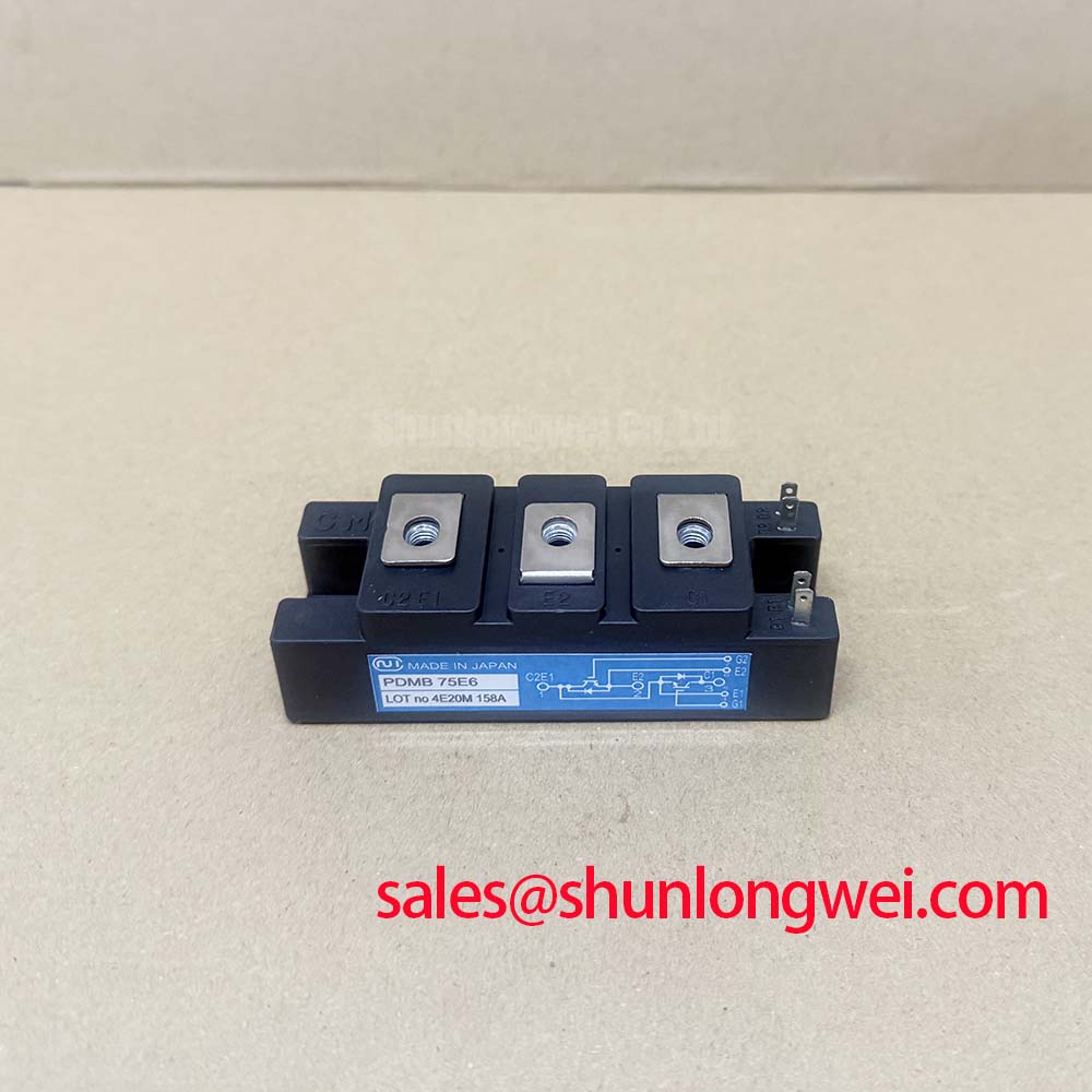
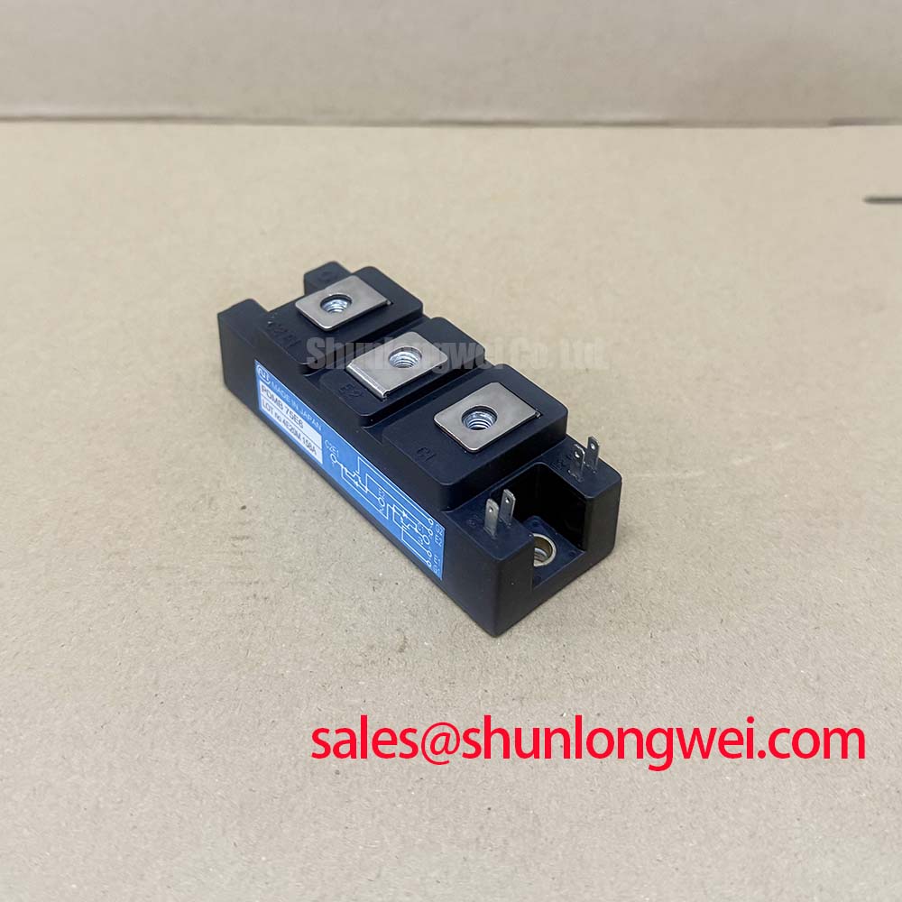
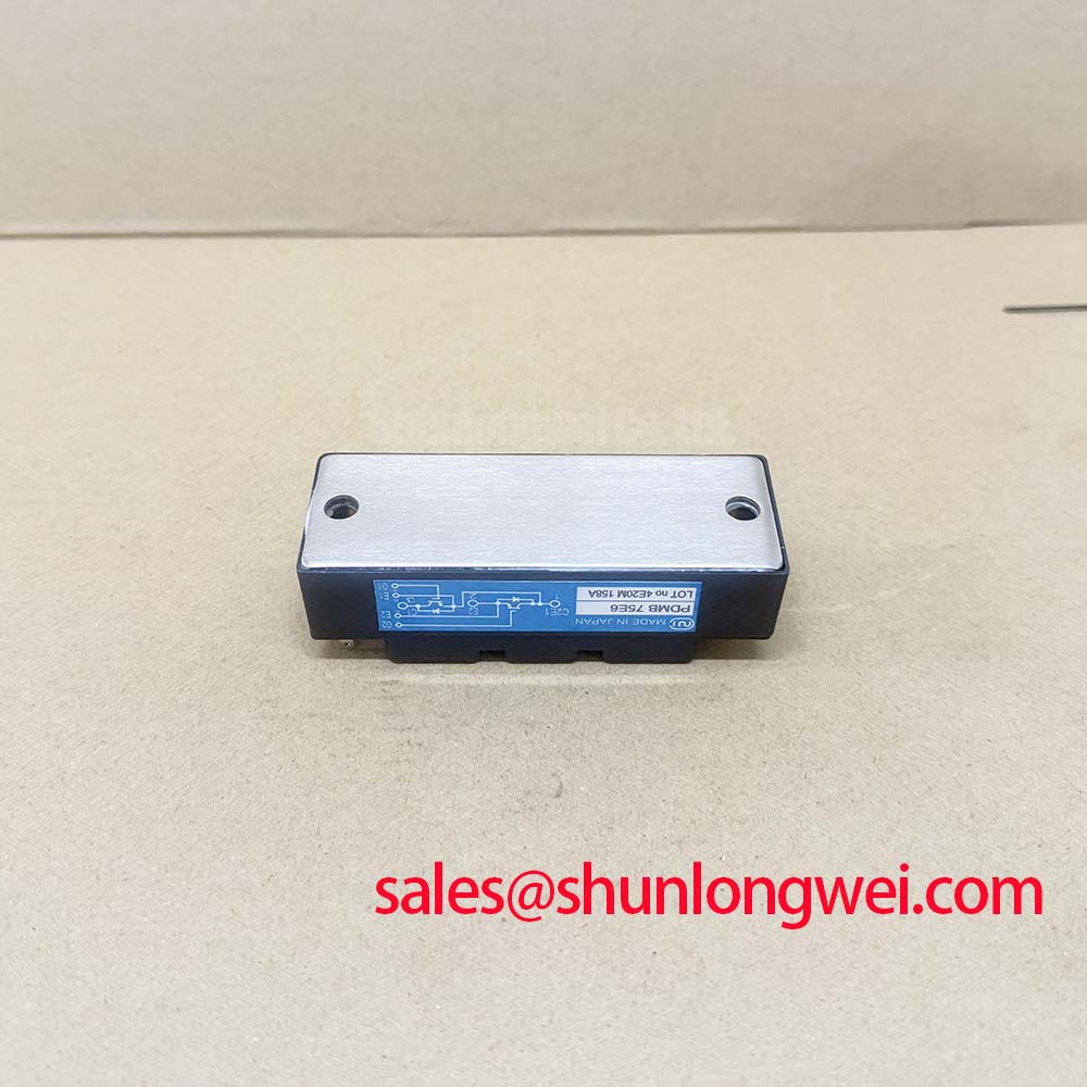
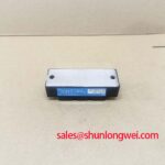
With the cabinet isolated and discharged, verify the PDMB75E6 terminal arrangement against the equipment schematic, inspect the case-to-heatsink contact area for contamination, and record cold-state diode readings before removing the original module from the power assembly. The PDMB75E6 from SanRex (Sansha Electric) is a power diode module specified with 600 V repetitive peak reverse voltage and 75 A average forward current. These Official Datasheet Specifications establish the electrical boundary for maintenance evaluation in controlled rectification and capacitor-switching power assemblies.
The module has an Official Datasheet Specification of 0.25 °C/W junction-to-case thermal resistance per device, a maximum junction temperature of 150 °C, and isolation voltage of 2500 V AC for 1 minute. Its forward surge capability is specified at 750 A at 50 Hz and 825 A at 60 Hz. These values should be treated as device-level limits rather than as direct operating targets for the surrounding grid-connected equipment.
| Official parameter | PDMB75E6 rating | Maintenance relevance |
|---|---|---|
| Repetitive peak reverse voltage, VRRM | 600 V | Confirm that measured line, capacitor-bank and transient conditions remain within the equipment’s validated voltage design. |
| Average forward current, IF(AV) | 75 A | Use for comparison with the original circuit loading and thermal loading record. |
| Peak forward surge current, IFSM | 750 A at 50 Hz825 A at 60 Hz | Relevant when reviewing fault-clearing coordination and inrush exposure. |
| Junction-to-case thermal resistance | 0.25 °C/W per device | Supports heat-path evaluation from semiconductor junction to the mounting surface. |
| Maximum junction temperature | 150 °C | Defines the published thermal ceiling, not a preferred continuous operating temperature. |
| Isolation voltage | 2500 V AC, 1 minute | Supports insulation coordination review within the complete equipment assembly. |
PDMB75E6 Circuit Protection & Reliability: Controlling the Rate of Rise of Reverse Voltage
Before returning a PDMB75E6 assembly to service, examine the snubber capacitors, damping resistors, bus connections, and protective-earth paths around the module. In capacitor-switching equipment, degraded suppression parts or loose laminated-bus joints can alter the voltage transient presented across a semiconductor during commutation. A diode module should be assessed as part of its installed circuit rather than as an isolated replacement item.
The 600 V VRRM rating is the Official Datasheet Specification for repetitive reverse blocking. It does not define a permitted overshoot level produced by capacitor discharge loops, stray inductance, or line disturbance. Design Consideration: RC snubbers and series saturable reactors are normally evaluated to moderate excessive rate of voltage rise and current rise, but their component values, voltage ratings, loss capability, and installation position must remain system-determined. The responsible engineer should validate the waveform at the module terminals with appropriately rated differential measurement equipment while checking peak voltage against the established DC-link and line-voltage design margins.
Do not infer reverse-recovery behavior, critical dynamic voltage capability, or switching performance from the ratings listed above. Those characteristics are not included in the supplied official data. Where a controlled-switch topology is involved elsewhere in the assembly, retain the original control-board timing and verify the manufacturer documentation for the installed circuit before altering snubber components or firing logic.
The published 0.25 °C/W per-device Rth(j-c) provides a useful thermal path reference during maintenance. It does not replace inspection of the full case-to-heatsink interface. Clean the mating face, inspect the thermal interface material for drying, displacement, or uneven spread, and ensure that the mounting hardware follows the original equipment’s documented torque requirement. ⚠️ Maintenance Note: Monitor terminal and heatsink contact temperature during normal loading and correct blocked airflow or degraded thermal-interface material before repeated thermal cycling causes further stress.
For a neutral cross-reference discussion, the FRS200CA100 can be reviewed as a separate module reference; its mechanical outline, terminal order, electrical ratings, and circuit function require independent verification and should not be presumed interchangeable with the PDMB75E6.
Transient Dynamics & Electrical Design: Fuse Total Clearing I2t versus Device Melt on PDMB75E6
A short-circuit investigation should begin with physical evidence: inspect semiconductor fuses, fuse clips, busbars, capacitor contactors, and the module mounting plane before assigning a fault cause. An open fuse can result from a module fault, but it can also follow an external bus fault, a capacitor-bank event, insulation contamination, or a control sequence problem. A measured record of the failed assembly is more useful than replacing a fuse and module without checking the surrounding branch.
The PDMB75E6 has published surge-current ratings of 750 A at 50 Hz and 825 A at 60 Hz. These Official Datasheet Specifications describe a peak forward surge condition under stated mains frequencies; they are not a published total clearing I2t rating and must not be converted into one without the relevant manufacturer curves and test conditions. Likewise, no fuse coordination table or semiconductor melt-energy value is provided in the supplied data for this module.
Engineering Recommendation: compare the selected semiconductor fuse’s pre-arcing and total-clearing I2t documentation with the device withstand information released for the actual circuit configuration. The review must include prospective fault current, conductor inductance, source impedance, branch topology, and the voltage present when the fuse opens. The objective is to ensure the protection path interrupts destructive fault energy before the semiconductor and adjacent conductors experience unacceptable stress. Final coordination belongs to the equipment designer or protection engineer because fuse performance changes with available fault current and installation conditions.
During preventive maintenance, inspect fuse-holder pressure, discoloration around bolted joints, and evidence of heat at cable lugs. Re-torqueing must follow the original equipment documentation and the hardware supplier’s requirements, not an assumed module mounting value. After reassembly, insulation checks should be performed only with procedures compatible with the complete power assembly. The module’s 2500 V AC for 1 minute isolation rating is an Official Datasheet Specification, but it does not establish the test voltage or acceptance criterion for every installed cabinet.
Benchtop Waveform Tuning: Mitigating Stress via High-Frequency Switching Loss Dissipation on PDMB75E6
When a repaired power section shows abnormal heating, audible noise, or unexplained fuse stress, capture voltage and current waveforms at the installed commutation path before changing suppression parts. Probe placement, probe bandwidth, grounding method, and the known-good reference path can materially affect the result. Observe whether the waveform changes with load, capacitor-bank state, line condition, or control command, then compare it with the equipment’s approved service information.
Reverse-recovery peak current and recovery time are important factors in diode commutation, yet no IRRM, trr, or soft-recovery characterization is included in the supplied official PDMB75E6 parameters. It would therefore be inaccurate to publish a switching-loss estimate or claim a specific recovery behavior for this part. Design Consideration: reducing parasitic loop inductance can limit inductive overshoot during current transfer, while suppression networks can shape ringing and associated conducted or radiated noise. The required layout, suppression approach, and permissible waveform remain dependent on the system’s operating frequency and measured switching behavior.
The 150 °C maximum junction temperature is an official absolute thermal boundary, not evidence that a module is thermally healthy at that temperature. Review fan operation, fin blockage, enclosure filters, thermal compound condition, and signs of condensation around the power stack. Radiative exchange can also contribute to enclosure heat balance, particularly where hot surfaces face each other; the underlying relationship is described by the Stefan–Boltzmann Law for Radiative Heat Exchange in Power Enclosures. This physical principle is useful for enclosure assessment but does not supply a thermal rating for the PDMB75E6 installation.
For service teams reviewing resonant or switched-load behavior, Resonant Topologies in Home Appliances provides contextual material on topology-dependent commutation behavior. The actual PDMB75E6 circuit must still be verified from its own schematic, installed waveform, and approved service procedure.
PDMB75E6 Circuit Protection & Reliability: Calibrating AC-to-DC Transfer Characteristics
AC-to-DC transfer behavior cannot be determined from the PDMB75E6 voltage and current ratings alone. In a diode rectifier, the average DC output varies with supply waveform, source impedance, load type, commutation overlap, and the configuration of the complete bridge. The resulting output also depends on the applied AC voltage and load conditions, so no specific output-voltage curve should be assigned to this module without the circuit schematic and verified system data.
This distinction matters when evaluating a grid-tied Static Var Compensator or a rectifier and capacitor-charging branch. The PDMB75E6 may be considered for compatibility assessment where its 600 V repetitive reverse voltage, 75 A average forward current, thermal path, isolation requirement, and terminal arrangement align with the original design. The integrator should verify line-to-line voltage, capacitor-bank switching duty, branch current, protective coordination, enclosure clearances, and the original manufacturer’s qualification requirements.
In a diode bridge, the operating system transfers portions of the available AC waveform to the DC side according to the supply, bridge configuration, source impedance, commutation behavior, and load. The resulting power factor and harmonic demand are system-level characteristics, not official performance claims for the PDMB75E6. Confirm these effects using the facility’s approved measurement method and applicable grid-interconnection requirements rather than attributing the results to a single semiconductor module.
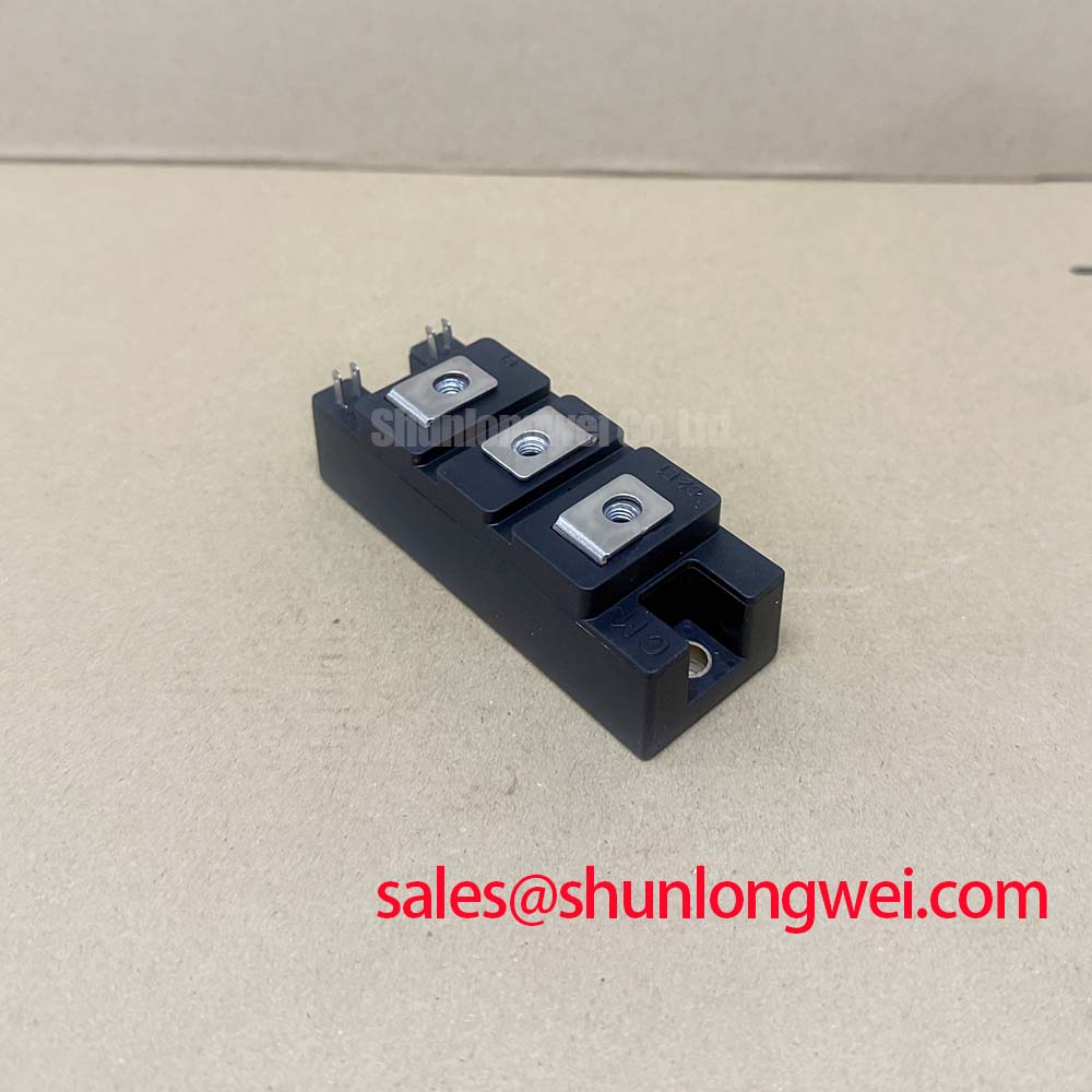
For a planned replacement, compare the original module marking, circuit position, terminal map, heatsink interface, protection branch, and rectifier function. Verify that the replacement evaluation retains the original voltage, current, isolation, thermal, and waveform requirements. This approach supports a disciplined repair decision without assuming that similar-looking modules share identical electrical behavior.