Content last revised on September 14, 2026
Assembly Integrity & Layout Architecture: Implementing Thermal Interface Material Spreading across SKKT500/08E
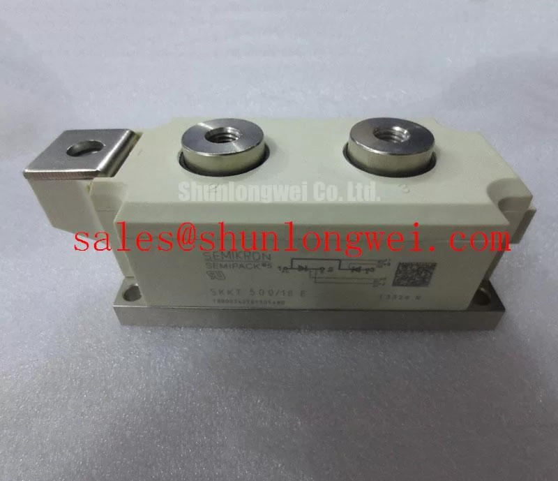
The module uses a SEMIPACK 5 package measuring 150 × 60 × 52 mm and precious metal pressure contacts according to the supplied manufacturer data. Its official maximum average on-state current is IT(AV) = 500 A at Tcase = 89°C, while the continuous RMS on-state current is IRMS = 920 A. These ratings do not replace a complete thermal assessment. The heatsink, airflow, mounting surface, busbar arrangement, and operating waveform all influence the case temperature used for evaluation.
The official thermal resistance is Rth(j-c) = 0.062 K/W per thyristor, with a maximum junction temperature of Tvj = 130°C. During installation, inspect the heatsink for flatness, contamination, burrs, and old thermal interface material. Apply the selected thermal compound as a thin, continuous film appropriate to the supplier’s instructions, then tighten the mounting hardware progressively so that contact pressure develops evenly across the baseplate. The objective is consistent thermal transfer without distorting the module body. The final mounting torque must be taken from the applicable Semikron mechanical documentation and hardware specification rather than assumed from the current rating.
Terminal connections should be clean, correctly positioned, and supported so that busbar weight does not load the module terminals. Designers should verify conductor clearance, creepage, clamp geometry, and the actual tightening specification against the original assembly drawing. After commissioning, compare temperature rise between corresponding phases under a controlled load. A localized increase may require inspection of contact pressure, interface material distribution, airflow, current sharing, or gate drive timing rather than replacement of the module alone.
Maintenance Note: Isolate the equipment before service, periodically remove dust from the heatsink and air path, and trend contact temperature to identify thermal interface aging or a loose power connection.
Benchtop Waveform Tuning: Mitigating Stress via Fuse Total Clearing I2t versus Device Melt on SKKT500/08E
The SKKT500/08E has an official repetitive peak off-state voltage and repetitive peak reverse voltage rating of VDRM and VRRM = 800 V. Its specified surge on-state current is ITSM = 15,000 A for 10 ms at Tvj = 130°C. ITSM is a device withstand specification under defined test conditions, not a permission to select a fuse by current rating alone. In a high-current green hydrogen electrolyzer DC power rectifier, the semiconductor protection study should include prospective short-circuit current, circuit inductance, line impedance, fuse operating time, and the complete fuse total-clearing I²t curve.
The correct coordination method is to obtain the applicable Semikron data for the module and compare the selected semiconductor fuse’s total clearing I²t with the device withstand information at the expected fault conditions. The supplied product information does not include a fuse coordination table or a module I²t limit, so those values must be verified from the relevant technical documentation before a protection claim is made. A fuse that interrupts the fault quickly may still expose the rectifier to damaging voltage overshoot if the physical layout produces excessive stray inductance.
On the bench, verify the gate and power waveforms with suitable differential and current probes. Capture the voltage across the module during turn-on, commutation, and fault interruption, then compare the measured peak with the system DC voltage and the 800 V repetitive rating. Minimize the high-current fault loop and keep the protection path physically coordinated with the rectifier terminals. The final fuse type, rating, and I²t margin remain system engineering decisions that require tested fault records, not inference from ITSM alone.
Field Diagnostics & Commissioning: Preventing Localized Gate Hotspot Burnout in SKKT500/08E Topologies
Commissioning should start with the original firing circuit disconnected from the power stage where practical. Confirm gate and cathode identification from the equipment schematic, inspect the gate wiring for poor crimping or unintended common impedance, and verify that the firing pulse reaches the module under the same reference conditions used by the controller. A gate waveform that looks correct at the driver output can differ at the device terminal because of cable inductance, isolation behavior, grounding, or connector condition.
The supplied engineering brief identifies gate pulse rise time, gate current, back-porch holding current, and multi-pulse firing as important review points. These are not included among the official SKKT500/08E ratings provided here, so the applicable Semikron gate trigger specifications must be checked before using values such as a gate current rise-rate target. Designers should verify reliable triggering across temperature, line phase position, and expected noise conditions while ensuring that the firing circuit does not exceed the documented gate limits.
When a module fails after commissioning, compare the suspect phase with a known-good phase using the same probe reference and load condition. Check pulse repetition, pulse width, gate return continuity, isolation barrier behavior, and commutation timing. A gate-side anomaly may coexist with excessive anode circuit overshoot, insufficient cooling, or an abnormal load current. The Field Engineer’s Handbook provides a useful technical framework for separating electrical, thermal, and installation evidence during failure analysis.
For a documented direct replacement assessment within the same broad power module family, engineers can review SKKH273/18E. Its voltage, current, package, gate requirements, terminal layout, and thermal data must be checked independently against the original circuit before any substitution decision.
SKKT500/08E Circuit Protection & Reliability: Evaluating Thyristor Commutation and Recovery Behavior
The SKKT500/08E is a thyristor-thyristor module, but the supplied official parameter set does not provide turn-off or recovery characteristics such as recovery time, recovery current, or related commutation curves. Those characteristics cannot be assigned from the 800 V voltage rating or the 500 A average current rating. For a rectifier feeding an electrolyzer DC bus, the system engineer should obtain the relevant dynamic curves and evaluate them at the actual junction temperature, commutation current, circuit inductance, and firing angle.
During waveform testing, monitor thyristor commutation voltage, current overlap, recovery behavior, and conducted or radiated disturbance at the equipment level. Minimize parasitic commutation loop inductance to reduce turn-off overshoot, then verify peak voltage against the system DC-link boundary during switching tests. Long motor or converter cables can create transmission-line effects and reflected voltage peaks, but the resulting stress depends on cable construction, termination, switching speed, and source impedance. Filtering and damping therefore require measured system behavior rather than a fixed value assigned to this module.
The official isolation capability is Visol = 3,600 V AC RMS for 1 second and 3,000 V AC RMS for 1 minute at 50 Hz. These are specified test ratings and should not be presented as an independent system safety certification. Insulation coordination, pollution level, enclosure conditions, altitude, condensation control, and clearance requirements must be evaluated for the completed rectifier assembly. Semikron’s SEMIPACK® thyristor and diode module information can be consulted alongside the exact product documentation when reviewing construction and dynamic behavior.
| Manufacturer | Semikron |
| Module type | Thyristor-thyristor module |
| VDRM and VRRM | 800 V |
| IT(AV) | 500 A at Tcase = 89°C |
| IRMS | 920 A |
| ITSM | 15,000 A for 10 ms at Tvj = 130°C |
| Rth(j-c) | 0.062 K/W per thyristor |
| Tvj maximum | 130°C |
| Isolation voltage | 3,600 V AC RMS for 1 second and 3,000 V AC RMS for 1 minute |
| Package | SEMIPACK 5, 150 × 60 × 52 mm |