Content last revised on September 14, 2026
SKKT500/14E Specifications
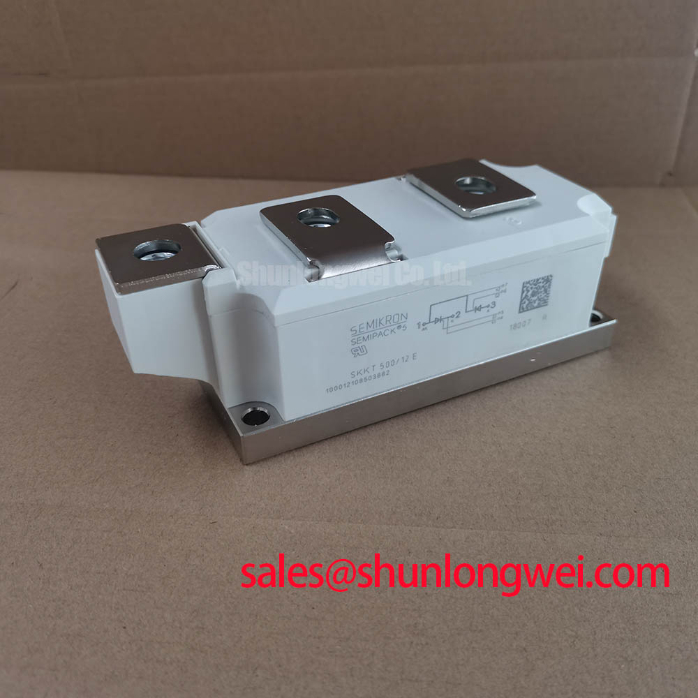
Before reconnecting a replacement unit, verify the nameplate voltage class, inspect the SEMIPACK 5 contact surfaces, and compare each thyristor path with the removed assembly using an isolated low-energy test method. SKKT500/14E is a Semikron dual-thyristor power module rated at VDRM/VRRM 1400 V and ITAV 500 A under Sin. 180 operation at a case temperature of 89°C, according to the official specification.
| Official Specification | Rating |
|---|---|
| Repetitive peak off-state and reverse voltage | 1400 V |
| Non-repetitive peak reverse voltage | 1500 V |
| Average on-state current | 500 A |
| RMS continuous on-state current | 920 A |
| Surge peak on-state current | 17,000 A for 10 ms at Tj = 25°C |
| Fusing rating | 1,445,000 A²s for 10 ms at Tj = 25°C |
| On-state voltage | 1.5 V maximum at Tj = 25°C and IT = 1700 A |
| Junction-to-case thermal resistance | 0.037 K/W per thyristor |
| Junction and storage temperature range | −40°C to +125°C |
Benchtop Waveform Tuning: Mitigating Stress via Pulse-Transformer Isolated Firing Circuit on SKKT500/14E
Use an isolated pulse-transformer firing circuit to observe gate-to-cathode pulse shape at the installed module rather than only at the controller output. Gate lead length, common return routing, and transformer coupling can alter the pulse seen at the device terminals. The provided official ratings define the main current, voltage, thermal, and dv/dt limits, but they do not define gate trigger current, gate pulse rise-time limits, or a required firing-pulse profile. These values should therefore be verified against the original equipment documentation and the applicable Semikron datasheet before drive changes are approved.
A multi-pulse firing approach is a Design Consideration where a phase-controlled bridge must retain predictable triggering through electrical noise, load variation, or transformer phase displacement. Scope the gate pulse, anode-cathode voltage, and load current together. A missing or distorted current pulse can arise from several locations, including pulse-transformer saturation, an incorrect firing reference, poor terminal contact, or an issue elsewhere in the bridge.
Fuse coordination should be reviewed against the official I²t rating of 1,445,000 A²s, while recognizing that fuse selection is system-determined by prospective fault current, coordination objectives, and the protection architecture. ⚡ Safety Interlock Note: Isolate the supply and confirm discharged energy-storage circuits before moving firing or power-terminal leads.
Transient Dynamics & Electrical Design: Interphase Transformer Current Balancing on SKKT500/14E
In high-current rectifier assemblies, engineers may evaluate the SKKT500/14E for six-pulse bridge legs or for bridges combined into twelve-pulse arrangements. An interphase transformer can support current sharing between parallel DC paths, but its effectiveness depends on matched firing references, transformer polarity, busbar resistance, commutation overlap, and the operating load. It should not be treated as a substitute for confirming current sharing with measured waveforms.
The module’s 920 A RMS continuous on-state-current rating and 500 A average on-state-current rating are official device ratings under stated conditions, not a declaration of DC output current for a complete rectifier. For a green hydrogen electrolyzer DC power rectifier, the system integrator should verify phase current, cooling conditions, conduction angle, and overload behavior at the actual heatsink temperature.
Where a lower-current member of the same family is being evaluated, the SKKT 250/14E provides a neutral reference point for comparing voltage class, current requirement, package compatibility, and thermal interface needs. The correct choice remains dependent on the original circuit topology and measured duty.
Field Diagnostics & Commissioning: Reverse-Recovery Behavior in SKKT500/14E Topologies
The SKKT500/14E is specified as a dual-thyristor module; the supplied official data does not provide diode reverse-recovery charge, reverse-recovery peak current, or recovery-time values for this model. Those characteristics must not be assumed for the module. In a line-commutated topology, reverse-recovery behavior belongs to the relevant commutating diode or external diode assembly and should be measured at operating temperature when it influences voltage ringing or conducted noise.
During commissioning, compare anode-cathode voltage, phase current, gate firing position, and heatsink temperature with a known-good channel or approved reference waveform. Changes in commutation shape may indicate several interacting causes, such as supply imbalance, altered snubber condition, transformer behavior, wiring inductance, or a device outside the SKKT500/14E branch.
For background on diode behavior used in associated rectifier stages, Semikron-Danfoss publishes information on CAL Diode Technology. A complementary rectifier component such as the SKKD81/14 should be assessed from its own published ratings and its actual position in the power circuit.
Transient Dynamics & Electrical Design: RC Snubber Network Optimization to Prevent Unintended Triggering on SKKT500/14E
The official critical off-state voltage rise rating for the SKKT500/14E is 1000 V/µs at Tj = 125°C. RC snubber networks and series reactors are Design Considerations used to manage the circuit conditions that can create excessive dv/dt, commutation ringing, and unintended thyristor triggering. Their component values cannot be prescribed from the module ratings alone because source inductance, transformer leakage, conductor geometry, load behavior, and switching state all affect the waveform.
Place the snubber loop to minimize parasitic inductance when suppressing commutation overshoot, then verify peak voltage and dv/dt margins by oscilloscope measurement at the module terminals during representative switching tests. A symmetrical laminated or closely coupled busbar arrangement is also an Engineering Recommendation where parallel current paths are present, because unequal loop impedance can disturb sharing and raise stress on one branch.
The 1.5 V maximum on-state voltage, specified at Tj = 25°C and IT = 1700 A, is useful for checking conduction-loss assumptions, while the 0.037 K/W junction-to-case thermal resistance per thyristor informs heatsink analysis. The mounting interface, thermal compound method, fastener torque, creepage layout, and cooling system must be verified against the original equipment instructions. For broader evaluation criteria covering thermal, electrical, and topology compatibility, consult the Power Semiconductor Selection Guide and Semikron-Danfoss information on SEMIPACK thyristor and diode modules.