Content last revised on September 14, 2026
Benchtop Waveform Tuning: Mitigating Stress via High Frequency Switching Loss Dissipation on SKKD81/14
With the equipment isolated and discharged, begin by checking the SKKD81/14 power terminals for abnormal low resistance in both polarities and inspect the insulated baseplate, terminal hardware, and case for cracking, heat marking, or uneven mounting pressure before reconnecting it to the circuit.
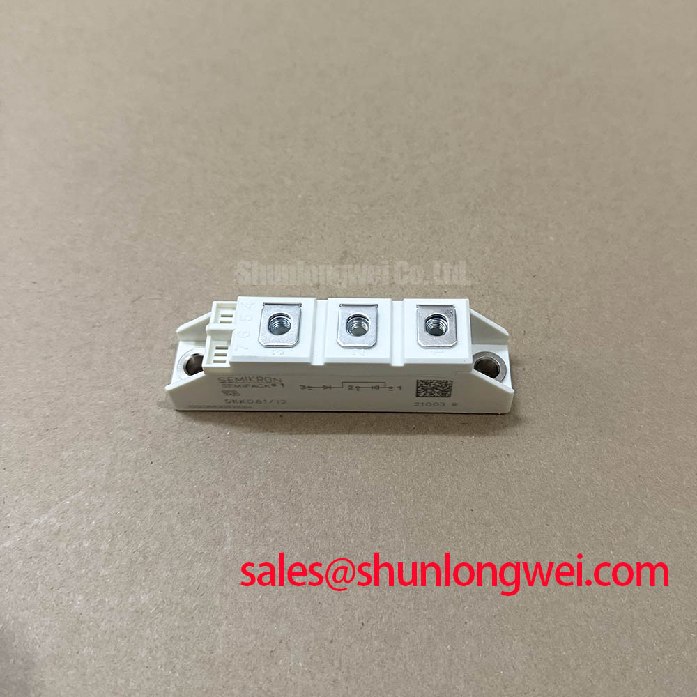
The Semikron SKKD81/14 is a dual diode power module rated at 1400 V repetitive peak reverse voltage and 82 A average forward current at Tc = 85 °C, according to the official datasheet specification. Its stated 1750 A surge forward current for 10 ms at Tvj = 125 °C is relevant when assessing short duration inrush and fault exposure, while the maximum 1.55 V forward voltage drop at IF = 300 A helps engineers estimate conduction loss under heavy current conditions.
The module has a specified junction to case thermal resistance of 0.4 K/W per diode and an isolation rating of 3000 V RMS for 1 minute. These ratings establish the electrical and thermal identity of the device, but they do not replace verification of the original circuit topology, fuse coordination, heat sink condition, wiring geometry, or control sequence.
For a stopped rectifier, capacitor switching assembly, or static var compensation cabinet, the first useful scope check is taken across the diode path during the actual commutation event. Confirm that the measured voltage waveform remains consistent with the original circuit arrangement and compare repeated events under equivalent loading. A diode module can pass a static meter test yet still show abnormal switching stress caused by external inductance, degraded snubber parts, loose bus connections, or a change in the associated thyristor firing pattern.
The official SKKD81/14 data supplied here defines voltage, current, surge, conduction, thermal, and isolation limits. It does not establish a specified reverse recovery peak current, reverse recovery time, or soft recovery factor. Those values should therefore not be assumed for this exact part. When waveform tuning is required, the system integrator should measure the commutating current and voltage with suitable differential and current probes, then compare the result with the equipment manufacturer’s known operating waveform.
Reverse recovery behavior can affect turn off stress in the commutating device and can contribute to conducted or radiated noise. This is a Design Consideration, not an official SKKD81/14 switching speed claim. Keep the current loop compact where practical, verify terminal contact quality, and inspect the existing RC network as a complete assembly rather than changing one element in isolation. The correct snubber values depend on the bus arrangement, line impedance, switching device characteristics, and measured transient response.
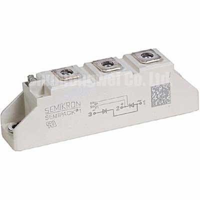
Semikron’s SEMIPACK® thyristor and diode module information provides useful product family context when reviewing module based power-stage arrangements. For SKKD81/14 service work, terminal identification must follow the equipment schematic and the module marking because a visually similar package does not establish identical internal diode configuration or connection assignment.
⚠️ Field Alert: Tighten electrical and mounting hardware only to the original equipment or module documentation requirements, and apply thermal compound as a uniform thin film so uneven pressure does not compromise heat transfer or insulation integrity.
Where an existing design review calls for a different current class or topology, engineers may document the physical and electrical differences against SKKT 250/14E as a separate thyristor module reference. It is not an automatic replacement for SKKD81/14 because the device function, terminal arrangement, triggering requirements, protection network, and thermal interface must all be confirmed at system level.
SKKD81/14 Circuit Protection & Reliability: Calibrating AC Line Surge Immunity, Lightning Transients
Before returning an AC connected power stage to service, examine the incoming protective chain from line terminals through disconnect hardware, surge suppression, semiconductor fuses, busbars, and the diode module. The SKKD81/14 is officially rated at 1400 V VRRM, which is the repetitive peak reverse voltage rating. It should not be interpreted as a complete surge immunity rating for the finished equipment.
Transient protection for an AC power assembly is a Design Consideration. Metal oxide varistors, RC snubbers, line reactors, capacitor discharge paths, and grounding practice have to be assessed as a coordinated network. Their required ratings depend on the measured line environment, installed cable lengths, upstream protection, capacitor bank configuration, and the transient waveform defined for the machine or installation. IEC 61000 4 5 is commonly referenced when equipment level surge immunity is evaluated, but a power semiconductor module alone should not be represented as independently compliant with an equipment EMC or surge standard.
In a grid tied static var compensator or thyristor switched capacitor installation, a transient captured at the line may appear at the module through multiple paths. Verify the condition of surge arresters, capacitor contactors or thyristor switching branches, control power grounding, and phase connections. A damaged suppression component, loose laminated bus structure, or wiring change may alter the stress seen by the diode even when the diode itself remains electrically functional in a cold test.
The official maximum 1.55 V VF at IF = 300 A is useful for understanding on state dissipation, but it is not a fixed operating drop across all currents and temperatures. Engineers should use measured operating current and case temperature to assess whether the thermal path is performing as expected. If temperature rise is inconsistent between parallel paths, inspect mounting flatness, heat sink cleanliness, interface material coverage, current sharing, and terminal resistance before assigning the issue to the module.
Semikron’s CAL diode technology reference can support broader discussion of diode technology, but only the published SKKD81/14 parameters should be used to identify this module in a maintenance record.
SKKD81/14 Thermal Electrical Optimization: Sinusoidal 10 ms Half Cycle Surge Current Practical Tuning
The SKKD81/14 has an official IFSM rating of 1750 A for 10 ms at Tvj = 125 °C. This figure describes a specified non repetitive surge capability under stated conditions. It is valuable during fault review and inrush analysis, but it is not a continuous current rating, a recurring pulse allowance, or a guarantee that every external fault event will be harmless.
When a unit has experienced a suspected line fault or capacitor bank event, record the protective device status and inspect the current path before applying reverse voltage again. Check for heat discoloration at lugs, damaged insulation, displaced busbars, and evidence that mechanical force has altered terminal alignment. Then test the diode paths with the equipment isolated. A comparison with an equivalent healthy phase can help identify an unusual result, although a static test cannot fully reproduce operating voltage and current stress.
The specified average forward current is 82 A at Tc = 85 °C. This condition makes case temperature central to the rating interpretation. The stated 0.4 K/W junction to case thermal resistance per diode describes heat flow from junction to case under the official specification conditions, while the final junction temperature in equipment also depends on the heat sink, interface quality, airflow or liquid cooling arrangement, enclosure temperature, load cycle, and neighboring heat sources.
As an Engineering Recommendation, evaluate thermal behavior from measured case temperature, actual load profile, and the original equipment thermal design. Do not infer a safe overload duration from the 10 ms surge figure. In capacitor switching equipment, repeated transient loading can be influenced by bank size, residual charge, switching timing, and network impedance. These conditions are determined by the system and should be verified during controlled testing.
For structured fault isolation and repeatable power semiconductor checks, the Field Engineer’s Handbook offers a related reference for measurement discipline, documentation, and reliability focused service practice.
SKKD81/14 Circuit Protection & Reliability: Calibrating Type 2 Coordination for Sub Cycle Dead Short Events
A dead short event develops faster than routine thermal protection can respond, so semiconductor fuse coordination must be reviewed as a complete protection problem. The SKKD81/14 official information provided here includes a 10 ms surge current rating of 1750 A, but it does not provide a fuse coordination table or a module specific I²t withstand value. A fuse selection cannot therefore be calculated from the published parameters listed on this page alone.
For a protection review, obtain the original circuit documentation, the fuse manufacturer’s time current and clearing I²t data, prospective fault current information, and the installed module configuration. The engineering objective is to ensure that the protective device limits fault energy before the semiconductor and surrounding conductors exceed their verified withstand conditions. This is an Engineering Recommendation; the resulting fuse type and rating are system determined and require validation against the actual fault path.
Do not treat the diode’s surge rating as a substitute for fuse clearing performance. The electrical energy delivered during a fault depends on source impedance, conductor layout, DC or AC topology, parallel paths, and the opening characteristic of the upstream device. A fuse may show no visible external damage while the circuit still requires a full inspection of terminal integrity, snubber components, busbar spacing, and connected thyristor branches.
For maintenance teams restoring an SVC or thyristor switched capacitor panel, retain the original coordination approach unless qualified engineering review approves a change. Verify the module’s 3000 V RMS isolation for 1 minute only within a controlled test procedure appropriate to the complete assembly. Isolation testing of the finished cabinet must account for connected electronics, surge suppressors, measurement circuits, and other components that may be affected by the applied test voltage.