Content last revised on October 10, 2026
Isolate the power assembly, verify that stored energy has discharged, and disconnect parallel current paths before checking the diode junctions of the SKKD81-16 with a multimeter. Compare forward and reverse readings with the circuit diagram and an equivalent healthy branch; an unexpected reading calls for further isolation, not an immediate diagnosis based on a single measurement.
The Semikron SKKD81-16 is a SEMIPACK diode module, not a gate-controlled thyristor assembly. The supplied reference values of 600.0 V and 811.0 A are not established here as official datasheet ratings and must not serve as installation limits. Resolve that specification discrepancy against the exact manufacturer datasheet before approving a replacement, protection setting, or operating voltage.
Transient Dynamics & Electrical Design: Mechanical Mounting Torque Sequence on SKKD81-16
Inspect the heatsink contact surface and the module mounting face before tightening the assembly. As a Design Consideration, contamination, surface damage, uneven clamping, and excessive thermal compound can impair heat transfer even when the external heatsink appears adequately cooled. Remove old interface material without damaging either mating surface, then apply the interface material according to the approved assembly procedure.
Junction-to-case thermal resistance describes only part of the heat path. Case-to-heatsink contact and heatsink operating temperature also influence junction temperature. For intermittent loading, assess the manufacturer’s transient thermal impedance information against the actual current waveform and pulse duration rather than treating steady-state thermal resistance as a complete transient model.
Use the mounting sequence and tightening torque specified for the exact module and fasteners. Terminal tightening and heatsink mounting are separate operations; neither value should be inferred from the other. Support busbars so their alignment does not load the module terminals or distort the assembly as bolts are tightened.
Field Alert: Do not pull a misaligned busbar into position by tightening the module terminal screw.
For fuse coordination, compare the fuse’s total clearing I²t with the module’s applicable manufacturer I²t limit under compatible voltage, temperature, and fault conditions. A matching continuous-current label alone does not establish semiconductor protection. The Semikron SEMIPACK thyristor and diode module range provides manufacturer context for the package family; the exact device documentation remains the basis for assembly limits.
Benchtop Waveform Tuning: Mitigating Stress via Diode Peak Reverse Recovery Current on SKKD81-16
Capture diode current and terminal voltage during the actual commutation event using suitably rated, correctly connected measurement equipment. As a Design Consideration, reverse-recovery peak current and recovery duration depend on operating current, junction temperature, and the imposed current transition. A cold resistance check cannot characterize this switching behavior.
Interpret reverse current together with the voltage waveform. Oscillation can involve the external commutation loop, measurement connections, and interacting circuit elements; it is not sufficient evidence of a defective module. Check probe arrangement and compare equivalent operating conditions before attributing ringing to the semiconductor.
Minimize unnecessary commutation-loop area to reduce inductive voltage stress, then validate the resulting waveform against the system’s permitted electrical limits. Any damping or snubber changes should follow measured behavior and the equipment design, rather than an assumed universal component value.
The manufacturer’s diode technology information offers background on its semiconductor portfolio, but does not establish CAL technology, fast-recovery performance, or a particular recovery specification for SKKD81-16. Maintenance records should retain operating conditions and measurement arrangements; the Field Engineer’s Handbook provides broader testing and failure-analysis context without replacing device-specific limits.
SKKD81-16 Operational Boundaries: Evaluating Three-Phase Back-to-Back Thyristor Voltage Limits
Trace the power circuit before treating SKKD81-16 as a replacement for a controlled switching module. A diode cannot perform the firing-angle control of a thyristor, and SKKD81-16 must not be evaluated as though it contains a back-to-back thyristor pair.
When assessing a high-voltage three-phase motor solid-state soft starter, first identify the module’s actual circuit role. Compatibility depends on the required rectification or conduction path, terminal arrangement, blocking-voltage capability, thermal conditions, and protection coordination. Motor starting current and torque depend on the controller, motor, supply, and load; this module alone establishes no guaranteed inrush reduction.
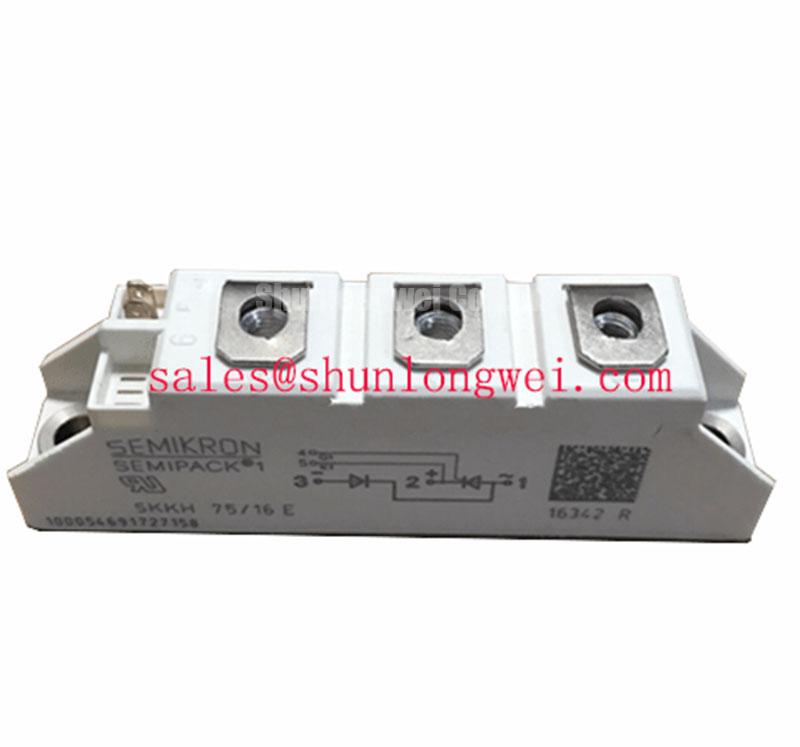
Compare the schematic symbols and terminal connections before comparing catalogue ratings. The related SKKH57-16E can be reviewed during a component-family assessment, but its presence in a related package family does not establish electrical interchangeability with SKKD81-16.
Before returning the assembly to service, verify terminal routing, busbar clearance, heatsink contact, and fuse identification against the equipment documentation. Conduct the equipment’s approved controlled restart and compare phase currents and module temperature behavior under equivalent conditions. Investigate any imbalance through the complete current path rather than assigning it automatically to the replaced module.